
Configuration method, configuration system, device, receiving method, receiving system and terminal

A configuration method and a technology for configuring a system, applied in the communication field, can solve problems such as increasing sending opportunities and high detection complexity

Active Publication Date: 2017-05-17
YULONG COMPUTER TELECOMM SCI (SHENZHEN) CO LTD
View PDF5 Cites 2 Cited by
  • Summary
  • Abstract
  • Description
  • Claims
  • Application Information

AI Technical Summary

Problems solved by technology

Compared with the second method, the advantage of this method is that the sending opportunity is further increased. The disadvantage is that the UE detection complexity is higher than that of the first method, and DCI signaling (Downlink Control Information, downlink control information) of the eNB (base station) may even be required. information) to further indicate the sending time of DRS

Method used


Image

  • Configuration method, configuration system, device, receiving method, receiving system and terminal
  • Configuration method, configuration system, device, receiving method, receiving system and terminal
  • Configuration method, configuration system, device, receiving method, receiving system and terminal

Examples


Embodiment Construction

[0110] In order to have a clearer understanding of the above objects, features and advantages of the present invention, the present invention will be further described in detail below in conjunction with the accompanying drawings and specific embodiments. It should be noted that, in the case of no conflict, the embodiments of the present application and the features in the embodiments can be combined with each other.

[0111] In the following description, many specific details are set forth in order to fully understand the present invention. However, the present invention can also be implemented in other ways different from those described here. Therefore, the protection scope of the present invention is not limited by the specific details disclosed below. EXAMPLE LIMITATIONS.

[0112] Figure 7 A schematic flowchart of a method for configuring a reference signal according to an embodiment of the present invention is shown.

[0113] like Figure 7As shown, a reference signa...


PUM


Abstract

The present invention proposes a reference signal configuration method and configuration system, a device with a base station function, a reference signal receiving method, a reference signal receiving system, and a terminal, wherein the reference signal The configuration method includes: setting at least one discovery reference signal in DMTC (DRS measurement time configuration); configuring transmission parameters for the at least one discovery reference signal; sending the transmission parameters to a terminal served by the device with base station function , so that the terminal receives the at least one discovery reference signal according to the sending parameter. Through the technical solution of the present invention, while increasing the DRS sending probability, the complexity of UE detecting DRS can be reduced as far as possible, so that the terminal can receive DRS accurately, thereby realizing frame synchronization and subframe synchronization.

Description

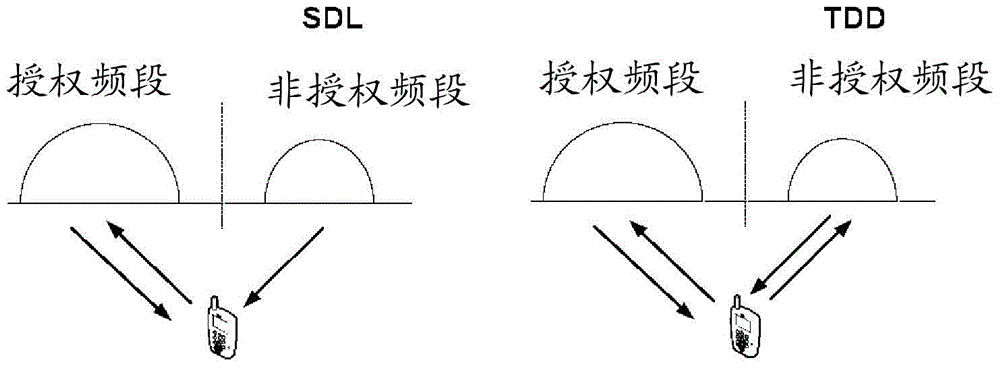
technical field [0001] The present invention relates to the field of communication technology, in particular, to a reference signal configuration method, a reference signal configuration system, a device with a base station function, a reference signal receiving method, and a reference signal receiving method system and a terminal. Background technique [0002] With the rapid increase of communication traffic, the authorized spectrum of 3GPP is increasingly insufficient to provide higher network capacity. In order to further improve the utilization of spectrum resources, 3GPP is discussing how to use unlicensed spectrum, such as 2.4GHz and 5GHz frequency bands, with the help of licensed spectrum. These unlicensed spectrums are currently mainly used by Wi-Fi, Bluetooth, radar, medical and other systems. [0003] Usually, access technologies designed for licensed frequency bands, such as LTE (Long Term Evolution, long-term evolution) are not suitable for use in unlicensed fr...

Claims


Application Information

Patent Timeline
Patent Type & Authority Patents(China)
IPC IPC(8): H04W72/08H04W56/00H04L5/00
CPCH04L5/0044H04L5/006H04W56/001H04W56/0045H04W72/0446H04L5/26H04B7/2662H04W72/54H04W72/23
Inventor 李明菊朱亚军张云飞
Owner YULONG COMPUTER TELECOMM SCI (SHENZHEN) CO LTD
Learn More