Automatic Arrangement Conveyor System for Glass Bottles

An automatic arrangement and conveying system technology, applied in the direction of conveyor objects, transportation and packaging, etc., can solve the problems of low yield of glass bottles and cans, residual stress of glass bottles and poor quality, etc., to improve yield, improve quality, Even heating effect

Active Publication Date: 2017-06-09
广东亿方包装制品有限公司
View PDF6 Cites 0 Cited by
  • Summary
  • Abstract
  • Description
  • Claims
  • Application Information

AI Technical Summary

Problems solved by technology

[0004] In order to solve the problems that the uneven spacing of glass bottles and cans on the mesh belt of the annealing kiln is prone to bursting during annealing, resulting in low yield of glass bottles and cans, residual stress and poor quality of glass bottles and cans, the invention provides a glass bottle Automatic arrangement and conveying system for glass bottles and cans. The automatic arrangement and conveying system for glass bottles and jars adopts a disc-type automatic arrangement device, a pneumatic bottle pusher and a sequentially controlled pneumatic valve. The bottles and cans are moved to the intermediate transition conveyor belt, and then the glass bottles and cans are pushed to the annealing kiln mesh belt by a pneumatic bottle pusher. The glass bottles and cans can achieve an ideal staggered state on the annealing kiln mesh belt. Uniformity, so that the glass bottles and jars are heated evenly during annealing, and the bottles will not burst during annealing, which improves the yield rate. At the same time, there will be no residual stress in the glass bottles and jars, which effectively improves the quality of the glass bottles and jars

Method used


Image

  • Automatic Arrangement Conveyor System for Glass Bottles
  • Automatic Arrangement Conveyor System for Glass Bottles
  • Automatic Arrangement Conveyor System for Glass Bottles

Examples


Embodiment Construction

[0018] The present invention will be further described below in conjunction with accompanying drawing:

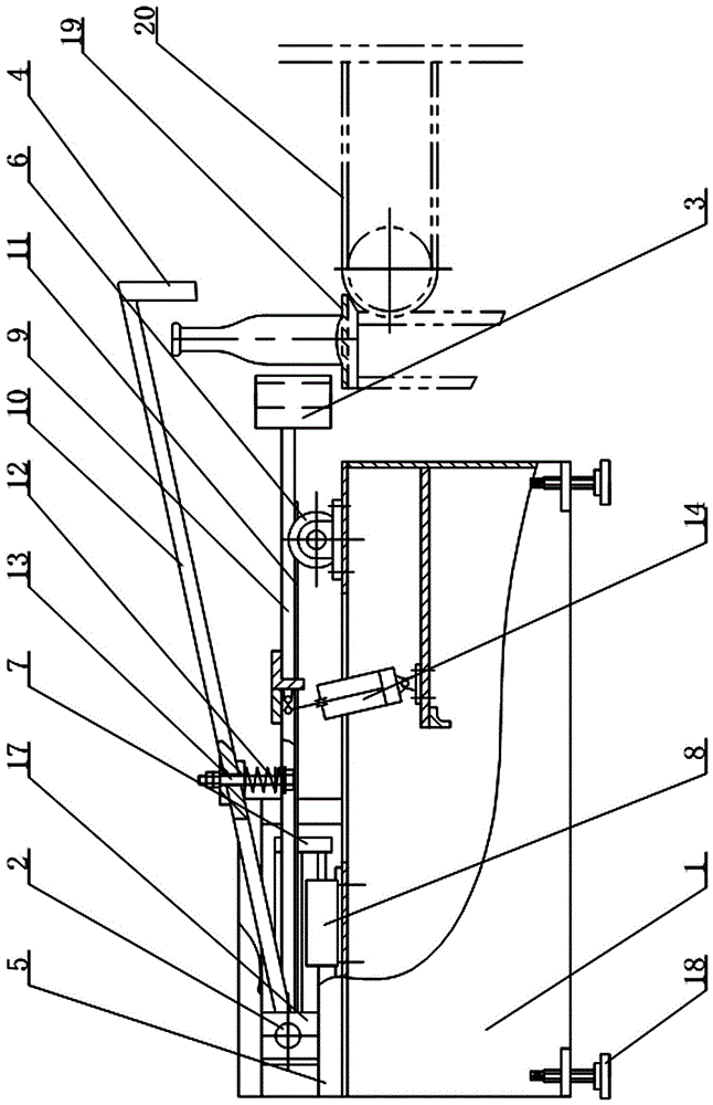
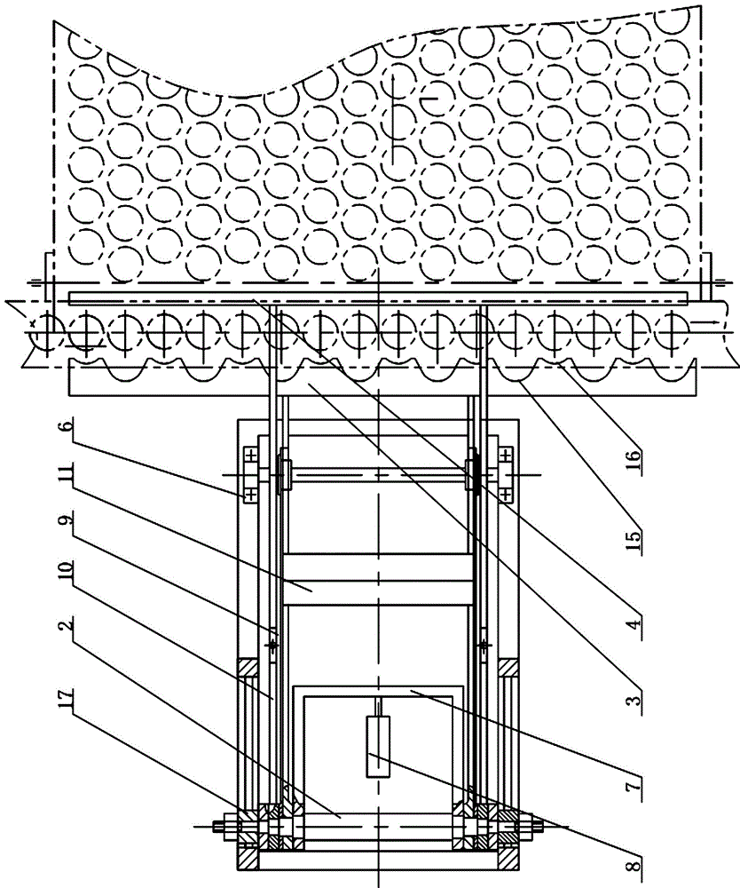
[0019] Depend on Figure 1 to Figure 6 As shown, an automatic arrangement conveying system for glass bottles and jars includes an automatic arrangement device, a pneumatic bottle pusher and a sequence control pneumatic valve. The automatic arrangement device is located between the output conveyor belt 21 and the transition conveyor belt 19 of the bottle forming machine. One end of the conveyor belt 19 is located at the annealing kiln mesh belt 20, and the pneumatic bottle pusher is placed on one side of the transition conveyor belt 9 and corresponds to the annealing kiln mesh belt 20. The pneumatic bottle pusher includes a frame 1, a central shaft 2. The push plate 3 and the guard plate 4 are provided with two slideways 5 and two rollers 6 above the frame 1. The two ends of the central shaft 2 are located in the slideway 5 and can slide along the slideway 5 in a straight li...


PUM


Abstract

The invention relates to an automatic arrangement and delivery system for glass bottles and jars. Mainly, the uneven spacing of glass bottles and cans on the mesh belt of the annealing kiln is prone to bottle explosion during annealing, resulting in low yield of glass bottles and cans, residual stress and poor quality of glass bottles and cans. It is characterized in that the automatic arrangement device is located between the output conveyor belt (21) and the transition conveyor belt (19) of the bottle forming machine, one end of the transition conveyor belt (19) is located at the annealing kiln mesh belt (20), and the bottle is pushed pneumatically The machine is placed on one side of the transition conveyor belt (19) and corresponds to the annealing kiln mesh belt (20). The glass bottle automatic arrangement conveying system pushes the glass bottle to the intermediate transition conveyor belt through the disc automatic arrangement device, and then pushes the glass bottle to the annealing kiln mesh belt through the pneumatic bottle pusher, and the glass bottle is in the annealing kiln The ideal staggered arrangement can be achieved on the mesh belt, and the distance between the glass bottles and jars is even, so that the glass bottles and jars are heated evenly during annealing, and the quality of the glass bottles and jars is effectively improved.

Description

technical field [0001] The invention relates to an automatic production line for making bottles and cans, in particular to an automatic arrangement and delivery system for glass bottles and cans. Background technique [0002] In the automatic bottle and can production line, glass bottle annealing is a very important process. The purpose of glass bottle annealing is to eliminate or weaken the residual stress in the glass bottle and can to the greatest extent and stabilize the internal structure of the glass bottle and can. At the same time, it can achieve better optical uniformity. In order to ensure that glass bottles and cans achieve better quality and a higher pass rate, during the transportation of glass bottles and cans from the bottle forming machine to the annealing kiln, scratches and extrusion deformation on the surface of glass bottles and cans should be avoided as much as possible. Moreover, the distance between adjacent glass bottles and jars should be kept as ev...

Claims


Application Information

Patent Timeline
Patent Type & Authority Patents(China)
IPC IPC(8): B65G47/32
Inventor 沈永松
Owner 广东亿方包装制品有限公司
Why Eureka
Try Eureka