Adjustable self-stabilization flow velocity reducer for pipe

An adjustable and self-stabilizing technology, applied in the direction of pipe components, pipes/pipe joints/fittings, mechanical equipment, etc., can solve problems such as pipeline occupation, product cost rise, impact, etc., and achieve the effect of achieving a stable range of flow velocity and achieving flow velocity

Inactive Publication Date: 2015-10-14
SHANGHAI UNIV OF ENG SCI
View PDF5 Cites 2 Cited by
  • Summary
  • Abstract
  • Description
  • Claims
  • Application Information

AI Technical Summary

Problems solved by technology

However, setting valves often affects other pipeline branches, and increasing the pipe diameter means that the pipeline needs to occupy more space, which reduces production efficiency and increases product costs

Method used


Image

  • Adjustable self-stabilization flow velocity reducer for pipe
  • Adjustable self-stabilization flow velocity reducer for pipe
  • Adjustable self-stabilization flow velocity reducer for pipe

Examples


Embodiment

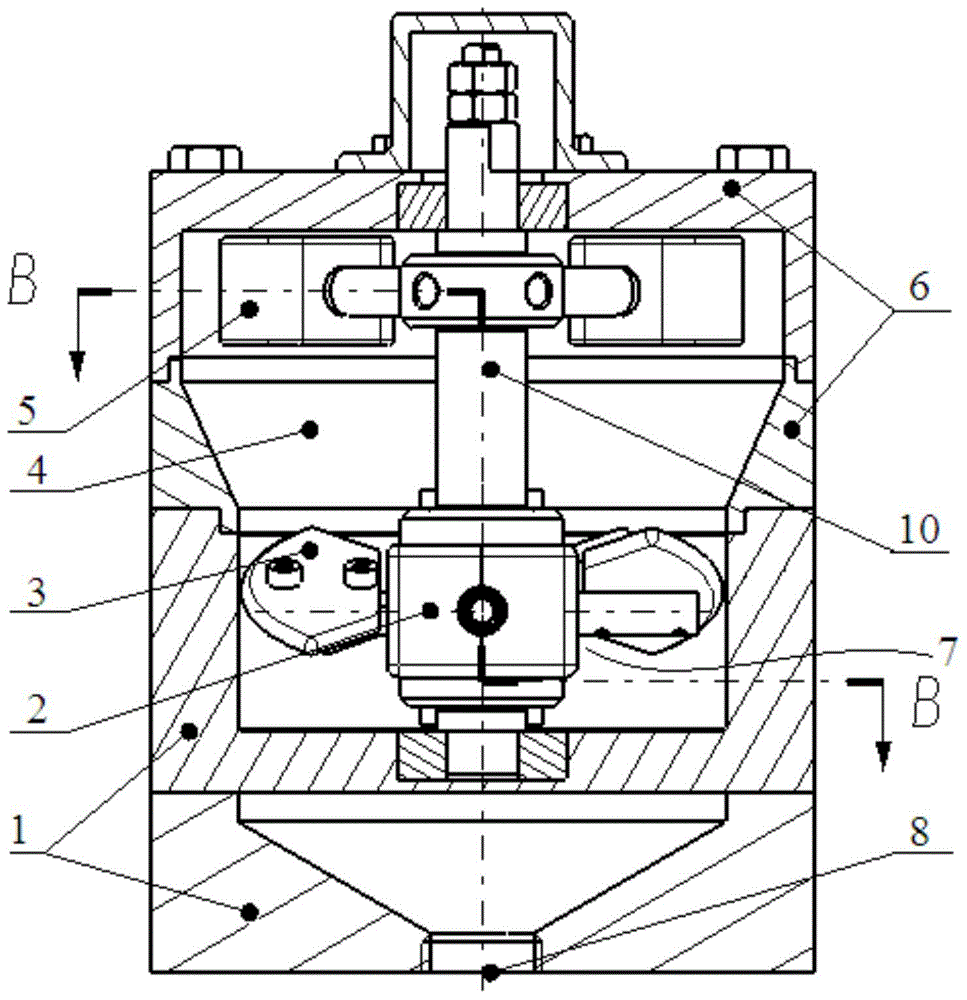
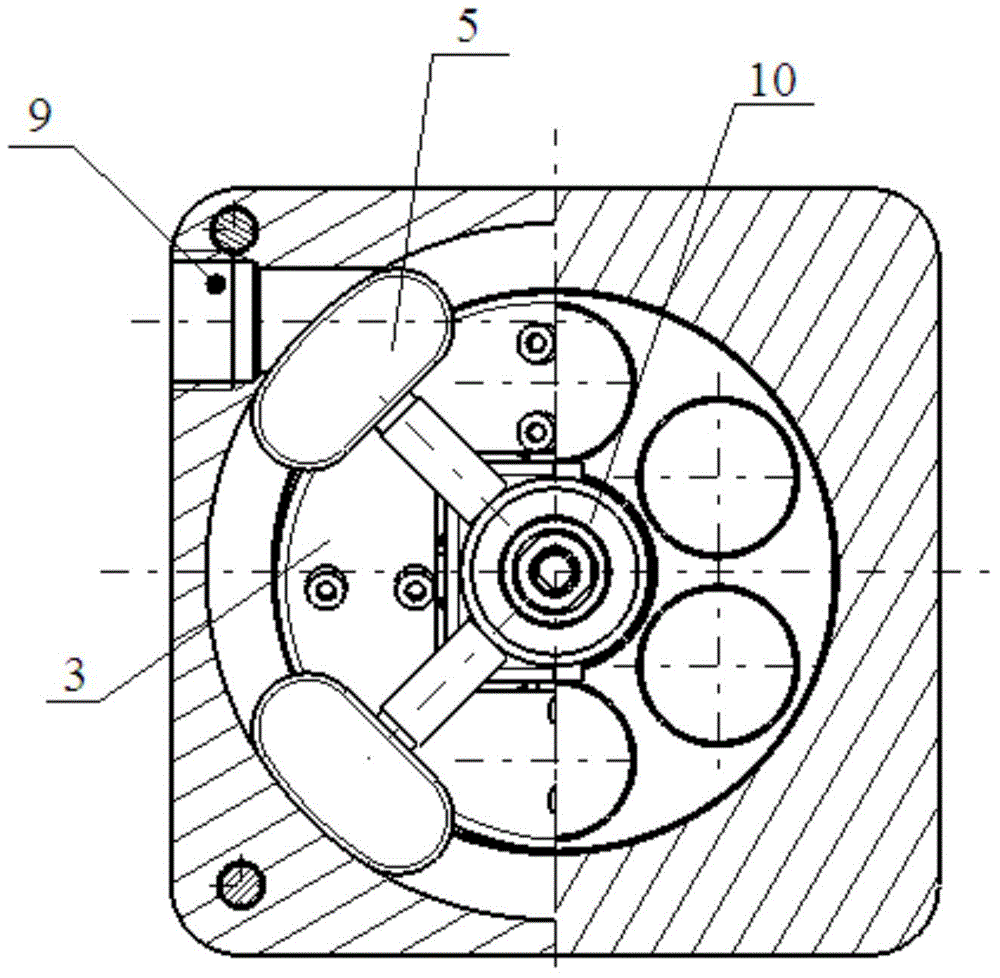
[0021] An adjustable self-stabilizing flow rate reducer for pipelines such as Figure 1 ~ Figure 2 As shown, the input mechanism 6 and the output mechanism 1 are included. After the input mechanism 6 is connected with the output mechanism 1, a cavity 4 is formed inside. The input mechanism 6 is provided with an inlet port 9, and the output mechanism 1 is provided with an outlet port 8. The port 9 and the outlet port 8 are respectively connected to the pipeline, and the cavity 4 is provided with a deceleration mechanism 7 .

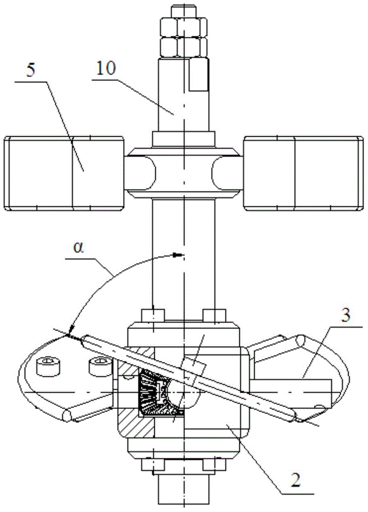
[0022] Such as image 3 As shown, the reduction mechanism 7 includes a main shaft 10, a plurality of blocks 5 arranged on the upper end of the main shaft 10, a runner 2 arranged on the lower end of the main shaft 10, and a blade 3 arranged on the runner 2, and the upper end of the main shaft 10 passes through The bearing is connected on the input mechanism 6, and the lower end is connected on the output mechanism 1 through the bearing. The runner 2 is si...


PUM


Abstract

The invention relates to an adjustable self-stabilization flow velocity reducer for a pipe. The flow velocity reducer comprises an input mechanism and an output mechanism, wherein a cavity is formed inside after the input mechanism is connected with the output mechanism; a flow inlet is formed in the input mechanism; a flow outlet is formed in the output mechanism; the flow inlet and the flow outlet are respectively connected with the pipe; a speed reducing mechanism is arranged in the cavity, and comprises a main shaft, multiple stoppers arranged at the upper end of the main shaft, a rotating wheel arranged at the lower end of the main shaft, and blades arranged on the rotating wheel; the stoppers are positioned at the back side of the flow inlet; the blades are positioned at the front side of the flow outlet; and the rotating wheel and the blades revolve under the flowing effect of a fluid. Compared with the prior art, the flow velocity reducer uses a method of blocking the flow inlet by the stoppers to realize the negative feedback adjustment between the fluid pressure and the flow velocity so as to realize a function of flow velocity self-stabilization; and included angles between the blades of the rotating wheel and the main shaft of the rotating wheel can be adjusted to change the remainder energy of the fluid in the flow outlet so as to realize the adjustment of the flow velocity in a stable range.

Description

technical field [0001] The invention relates to a flow velocity regulating device, in particular to an adjustable and self-stabilizing flow velocity reducer for pipelines. Background technique [0002] Fluids are ubiquitous in industrial production, including the most widely used water, lubricating oil necessary for the operation of mechanical equipment, and some liquids required for specific production, such as industrial alcohol, concentrated sulfuric acid, etc. In production, the transportation of liquid fluid is often realized by pipelines, but this will cause a problem-the flow and flow velocity are not easy to control, and often near the source, the pressure of the liquid fluid is high, resulting in a large flow and velocity. It is a problem that has been wanted to be solved in industrial production but has not been well solved to provide a specific place with a flow rate and a flow rate that meets the requirements without affecting other places. [0003] At present, ...

Claims


Application Information

Patent Timeline
IPC IPC(8): F16L55/00
CPCF16L55/00
Inventor 陈学森宋芳盛超杰凌俊峰李朋笑
Owner SHANGHAI UNIV OF ENG SCI
Why Eureka
Try Eureka