Friction stir welding fixture and temperature field feedback control method

A friction stir welding and feedback control technology, applied in welding equipment, manufacturing tools, non-electric welding equipment, etc., can solve the problems of large thermal deformation and vibration of welded parts, and achieve the effect of negative feedback adjustment

Pending Publication Date: 2020-06-09
JILIN UNIV
View PDF11 Cites 5 Cited by
  • Summary
  • Abstract
  • Description
  • Claims
  • Application Information

AI Technical Summary

Problems solved by technology

[0004] However, in the welding process of friction stir welding, due to the large heat input of friction stir welding, the welded parts of friction stir welding will produce large thermal deformation and even vibration.

Method used


Image

  • Friction stir welding fixture and temperature field feedback control method
  • Friction stir welding fixture and temperature field feedback control method
  • Friction stir welding fixture and temperature field feedback control method

Examples


Embodiment Construction

[0044] The present invention will be further described in detail below in conjunction with the accompanying drawings, so that those skilled in the art can implement it with reference to the description.

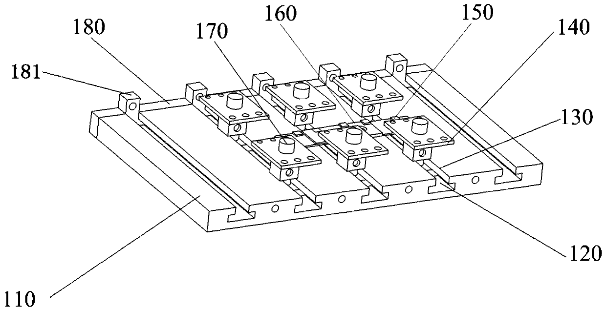
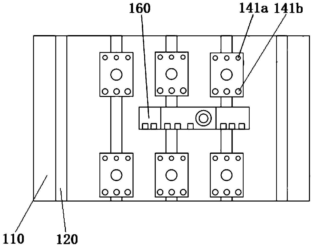
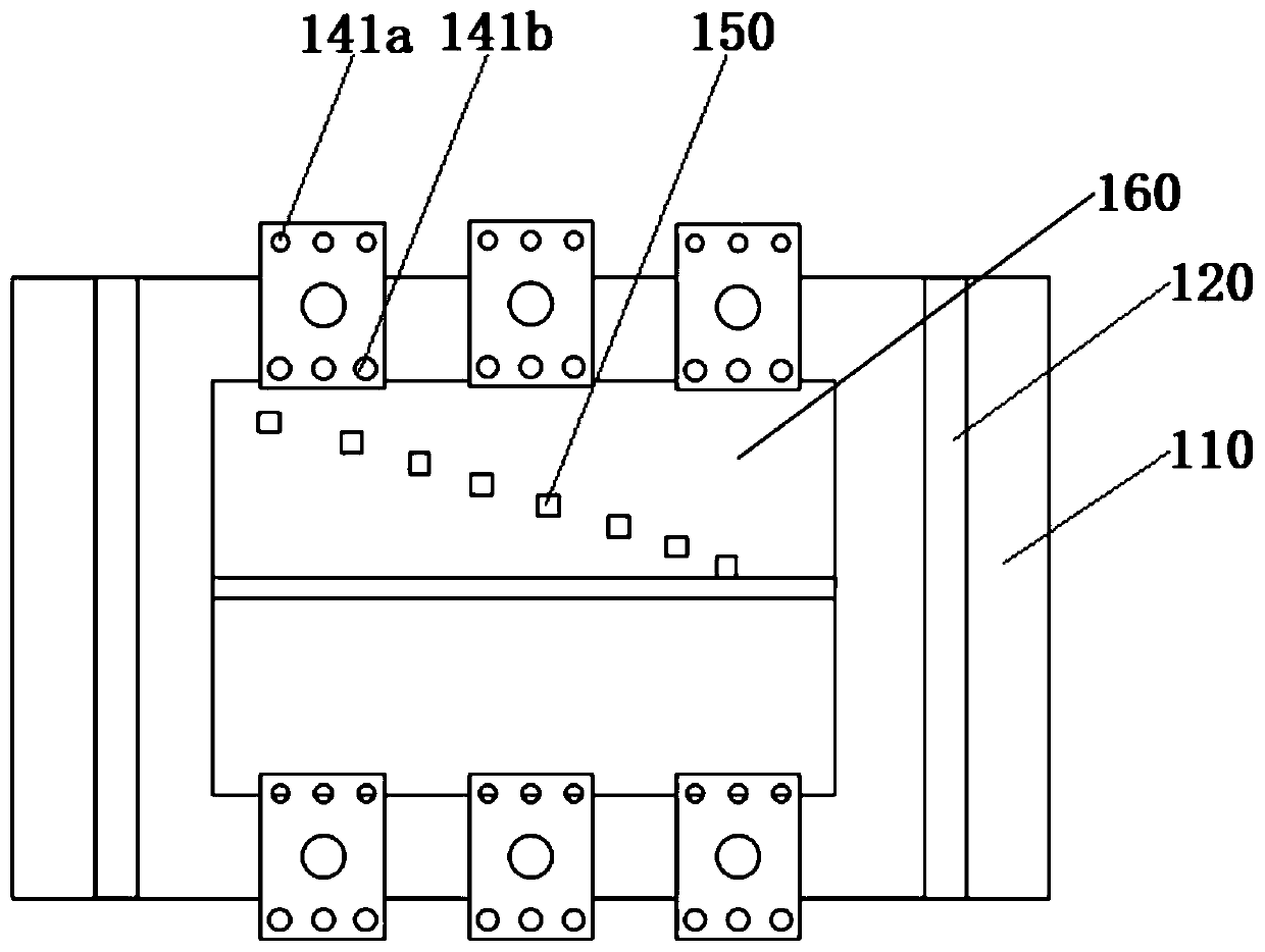
[0045] Such as Figure 1-6 As shown, the present invention provides a friction stir welding fixture, including: a base 110, a chute 120, a sleeve 130, a fixed block 140, a thermocouple 150, a unit to be welded 160, a slider 170, a side baffle 180 and a side fixing Block 181.

[0046] Such as Figure 1-3 As shown, the base 110 is placed horizontally on the ground. On the base 110, a plurality of chute 120 is provided. On the chute 120, a slider 170 is matched. The slider 170 has an external thread, and the sleeve 130 has an internal thread. , the sleeve 130 is matched and sleeved at the external thread. The fixed block 140 is provided with a circular hole, the fixed block 140 is arranged on the top of the sleeve 130, and is placed on the slide block 170, and the fixed block...


PUM


Abstract

The invention discloses a friction stir welding fixture. The friction stir welding fixture comprises a base, a plurality of sliding chutes, a plurality of slide blocks, a plurality of sleeves, a plurality of fixing blocks and a plurality of fixing hole units, wherein the plurality of sliding chutes are formed in the base; the plurality of slide blocks are arranged on the sliding chutes in a matching way, and can slide along the sliding chutes; the slide blocks are provided with external threads; the plurality of sleeves are provided with internal threads, and are arranged on the external threads in a matching way; lower surfaces of the sleeves are in contact with or positioned above an upper surface of the base; the plurality of fixing blocks are arranged on the tops of the sleeves, and are rotatably connected with the slide blocks; and the plurality of fixing hole units are formed in the fixing blocks, and are used for fixing welding units. The friction stir welding fixture is provided with a slide rail type device, and the slide blocks can be moved freely for friction stir spot welding of welding units with relatively small base materials, and can be fixed at positions where angles of the welding units are inconvenient to adjust. The invention further provides a temperature field feedback control method for the friction stir welding fixture.

Description

technical field [0001] The invention relates to a friction stir welding fixture and a temperature field feedback control method, belonging to the field of welding. Background technique [0002] As a solid phase joining process, friction stir welding is widely used in the joining of aluminum alloys, magnesium alloys and other metals. The heat generated by the friction between the high-speed rotating welding tool and the workpiece is used to locally melt the material to be welded. When the welding tool moves forward along the welding interface, the plasticized material is moved from the front of the welding tool under the action of the rotating friction of the welding tool. The part flows to the rear and forms a dense solid-phase weld under the extrusion of the welding tool. [0003] Compared with conventional friction welding, friction stir welding is not limited by shaft parts, and can carry out butt joint, lap joint, fillet joint and position welding of plates. Compared w...

Claims


Application Information

Patent Timeline
Patent Type & Authority Applications(China)
IPC IPC(8): B23K20/12B23K20/26
CPCB23K20/126B23K20/26
Inventor 陈鑫杨立飞于贵申王佳宁潘凯旋
Owner JILIN UNIV
Why Eureka
Try Eureka