Protective cover for portable terminal and method for manufacturing same

A terminal and protective cover technology, applied in the field of protective cover, can solve the problems of increased manufacturing cost, easy damage, complex process, etc., and achieve the effect of preventing antenna pattern disconnection, preventing deformation or breakage, and improving antenna performance

Active Publication Date: 2015-10-14
AMOGREENTECH CO LTD
View PDF7 Cites 3 Cited by
  • Summary
  • Abstract
  • Description
  • Claims
  • Application Information

AI Technical Summary

Problems solved by technology

[0005] But, the antenna that this exterior type is arranged on the portable terminal and is used for receiving the ground wave DMB needs to be stretched to the outside during use, so it is inconvenient to use, and because protrudes from the portable terminal quite a large part, thereby It has the following problems: it is not convenient to carry the terminal, and it is easy to be damaged during the use of the portable terminal, so it is necessary to pay attention to safe use at all times
[0009] In the conventional portable terminal described above, it is necessary to laminate the electromagnetic wave shield between the synthetic resin and the inner skin of the fabric before attaching it, so there are problems in that the process is complicated and the manufacturing cost is increased
[0011] As for the existing DMB antenna, conductive fibers are used on the accessory body, and the conductive fibers cover the surface of the matrix fiber with conductive polymers. Therefore, the problem is that compared with directly using conductive metal substances, Degraded signal reception performance
[0012] In addition, during the process of weaving conductive fibers into antenna patterns, the conductive polymers covering the matrix fibers may be peeled off, and the following problems may arise: after the conductive polymers are peeled off and broken unable to function as an antenna

Method used


Image

  • Protective cover for portable terminal and method for manufacturing same
  • Protective cover for portable terminal and method for manufacturing same
  • Protective cover for portable terminal and method for manufacturing same

Examples


Embodiment Construction

[0055] Embodiments according to the present invention will be described in detail below with reference to the accompanying drawings. In the process, the size, shape, etc. of the constituent elements shown in the drawings may be exaggerated for clarity and convenience of description. In addition, the terms specifically defined in consideration of the constitution and operation of the present invention may vary depending on the user's or operator's intention or practice. The definitions of the terms should be defined based on the contents of the present invention as a whole.

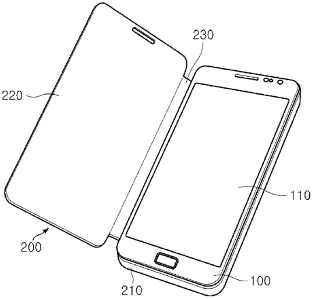
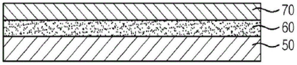
[0056] figure 1 It is a perspective view of a portable terminal equipped with a protective cover according to an embodiment of the present invention. figure 2 is a sectional view of the protective cover according to the first embodiment of the present invention.

[0057] refer to figure 1 , according to an embodiment of the present invention, the portable terminal includes: a terminal body 100, which ...


PUM


Abstract

A protective cover for a portable terminal, according to the present invention, can block electronic waves generated by the portable terminal and carries out an antibiotic function of removing various kinds of bacteria on the portable terminal by comprising: a cover layer; an adhesion layer stacked on the inner surface of the cover layer; and a metal layer attached to the adhesion layer so as to carry out an electronic wave shielding function. In addition, the present invention can carry out a DMB reception antenna function when the metal layer is formed in a DMB reception antenna pattern.

Description

technical field [0001] The present invention relates to a protective cover which is installed on the outside of a portable terminal so as to protect the portable terminal from external impact or contact, and more particularly relates to a protective cover for a portable terminal which has electromagnetic wave shielding , antibacterial, or an antenna (antenna) function for receiving Digital Multimedia Broadcasting (DMB, Digital Multimedia Broadcasting). technical background [0002] Generally, a portable terminal is a portable electronic device, which is portable and has at least one or more functions such as audio and video call functions, input / output information functions, and data storage functions. [0003] With the diversification of existing functions, the portable terminal is embodied in the form of a multimedia player (Multimedia player), and the multimedia player has complex functions, such as taking photos or videos, playing music or video files, playing games, etc...

Claims


Application Information

Patent Timeline
Patent Type & Authority Applications(China)
IPC IPC(8): A45C11/00
CPCB32B33/00B32B37/24B32B2305/38B32B2311/08H01Q1/243H01Q1/526H01Q7/00H05K9/009D02G3/441B32B7/12B32B5/028B32B5/024B32B5/26B32B15/04B32B15/14B32B2262/103B32B2307/202B32B2307/212B32B2457/00B32B37/14Y10T428/12035Y10T428/12444Y10T428/31678Y10T442/126Y10T442/629Y10T442/658Y10T442/339Y10T442/3415H01Q9/0407B32B2264/105
Inventor 宋容卨石钟洙金文会元民豪
Owner AMOGREENTECH CO LTD
Why Eureka
Try Eureka