Single-unit single-person-on-duty thermal power single-control console

A single console and unit technology, applied in the direction of electrical program control, comprehensive factory control, comprehensive factory control, etc., can solve problems such as the inability to realize single-person operation station thermal power units

Inactive Publication Date: 2018-03-02
刘伟
View PDF3 Cites 0 Cited by
  • Summary
  • Abstract
  • Description
  • Claims
  • Application Information

AI Technical Summary

Problems solved by technology

[0003] The purpose of the present invention is to solve the problem that one thermal power unit cannot be controlled by a single operator at the operating station, thereby providing a thermal power generation single control room for a single unit and one person on duty

Method used


Image

  • Single-unit single-person-on-duty thermal power single-control console
  • Single-unit single-person-on-duty thermal power single-control console
  • Single-unit single-person-on-duty thermal power single-control console

Examples


specific Embodiment approach 1

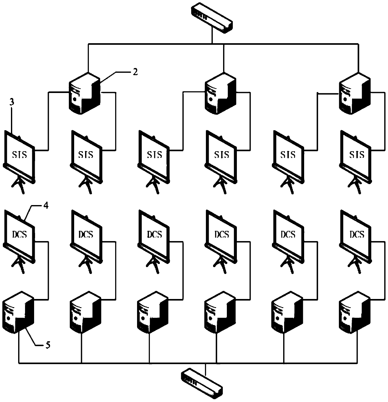
[0025] Specific implementation mode 1. Combination Figure 1 to Figure 4 Illustrate this specific implementation mode, the single control station of thermal power generation with single unit on duty, which includes A real-time database client computers 2, A or 2A real-time database client displays 3, B DCS operating stations 5 and B A DCS display 4; A and B are both positive integers;

[0026] The A real-time data client computers 2 are all connected to the MIS network; the display signal input terminals of each or two real-time data client displays 3 are connected with the display signal output terminals of a real-time data client computer 2;

[0027] The B DCS operation stations 5 are all connected to the DCS network, and the display signal input ends of the B DCS operation stations 5 are respectively connected with the display signal output ends of the B DCS displays 4;

[0028] It is characterized in that: A or 2A real-time data client displays 3 are arranged in a row or ...

specific Embodiment approach 2

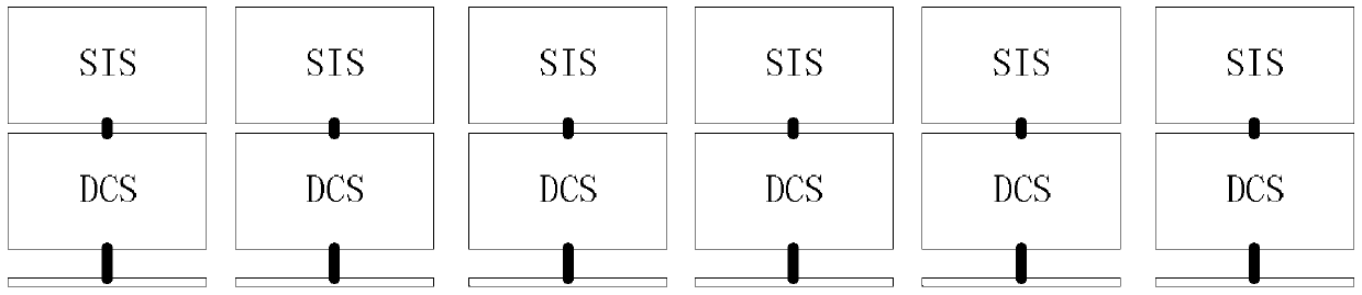
[0033] Specific Embodiment 2. The difference between this specific embodiment and the single-unit, single-person-attended thermal power generation single console described in specific embodiment 1 is that it also includes a double-layer display bracket, and the double-layer display bracket A or 2A real-time data client displays 3 are placed on the upper layer of the double-layer display bracket; B DCS displays 4 are placed on the lower layer of the double-layer display bracket.

specific Embodiment approach 3

[0034] Specific embodiment three, the difference between this specific embodiment and the single-unit single-person duty thermal power single console described in specific embodiment one is that the trend screen of the trend screen generation module on the real-time database client display 3 is divided into four Each area displays a group of power generation trends, and each group of power generation trends displays 15 to 25 power generation trend curves.


PUM


Abstract

The single-unit single-person-on-duty single-control console for thermal power generation relates to the layout and application of the operating console in the unit control room of a thermal power plant. The present invention is mainly composed of: DCS operation station, real-time database client, double-layer display bracket, and display. The real-time database system selects a system with independent development function to develop various monitoring screens required. The developed screens mainly include: Trend screen, process control screen and indicator monitoring screen, one main controller monitors the contents of the upper and lower displays, and three trend screens are placed on the upper display, which can monitor the changes of 300-500 data trends at the same time, improving the monitoring efficiency of operating personnel , timely discover the abnormal condition of the unit, and take necessary intervention to ensure the safe and stable operation of the unit. The lower display is used for DCS control, combined with the alarm system, one person can control one unit.

Description

technical field [0001] The present invention relates to the arrangement and application of the control room console of a thermal power plant, according to the International Patent Classification Table (IPC), it belongs to the electrical department, electric power generation, transformation or distribution branch, monitoring console or panel items or equipment for centralized control or display technical field. Background technique [0002] At present, the existing and previous technologies on monitoring consoles or panels for centralized control or display have all done very effective efforts to meet the needs of thermal power plant unit control room operating consoles, and have also designed many excellent technical solutions. But there are still deficiencies, and it is impossible to realize that a single person can control a thermal power unit using the operation station. Contents of the invention [0003] The present invention aims to solve the problem that it is curre...

Claims


Application Information

Patent Timeline
Patent Type & Authority Patents(China)
IPC IPC(8): G05B19/418
CPCY02P90/02
Inventor 刘伟
Owner 刘伟
Why Eureka
Try Eureka