a smart lock

A smart lock and a motor technology, applied in building locks, non-mechanical transmission-controlled locks, time registers, etc., can solve the problems of fingerprint locks that are prone to failure, poor security, and difficult to guarantee quality stability

Inactive Publication Date: 2017-10-10
谢庆文
View PDF4 Cites 0 Cited by
  • Summary
  • Abstract
  • Description
  • Claims
  • Application Information

AI Technical Summary

Problems solved by technology

[0002] At present, most of the locks on the anti-theft door are locked and unlocked by the key, and some are locked by lifting the outer handle upwards by hand. When opening the door, use the key to rotate the center wheel of the lock cylinder several times to unlock. This method is mechanical locking. And unlocking, the problem of mechanical lock is: its mechanical key is easy to be copied, so the security is very poor
[0003] However, many existing fingerprint locks install the drive motor in the heart of the door lock—the mortise lock body. Since the mortise lock body will withstand huge vibrations every time the door is closed and opened, it is more difficult to guarantee the quality stability. Moreover, the traditional motor drive structure produces friction, which makes the fingerprint lock prone to failure and seriously affects the service life of the door lock.
In addition, many fingerprint lock mortise lock bodies still adopt the lifting lock body (that is, the large tongue is ejected by lifting the handle outside the room), because vulnerable groups (such as the elderly and children) will forget to lock the door when opening and closing, leaving behind Hidden dangers of tailgating burglary

Method used


Image

  • a smart lock
  • a smart lock
  • a smart lock

Examples


Embodiment Construction

[0017] In order to make the technical problems, technical solutions and beneficial effects solved by the present invention clearer, the present invention will be further described in detail below in conjunction with the accompanying drawings and embodiments. It should be understood that the specific embodiments described here are only used to explain the present invention, not to limit the present invention.

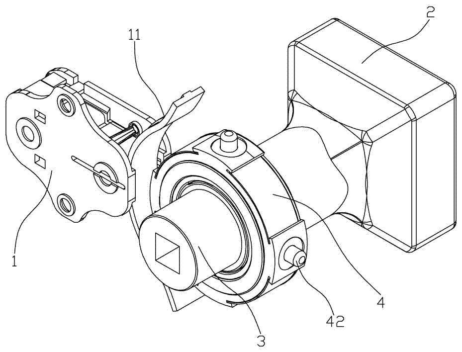
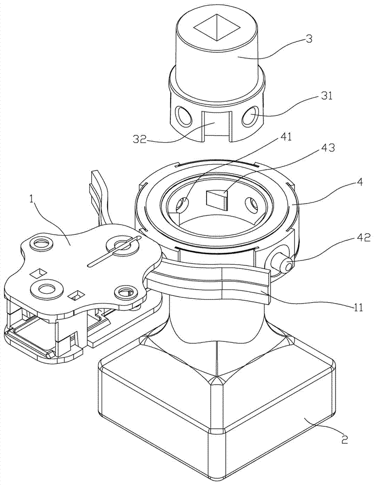
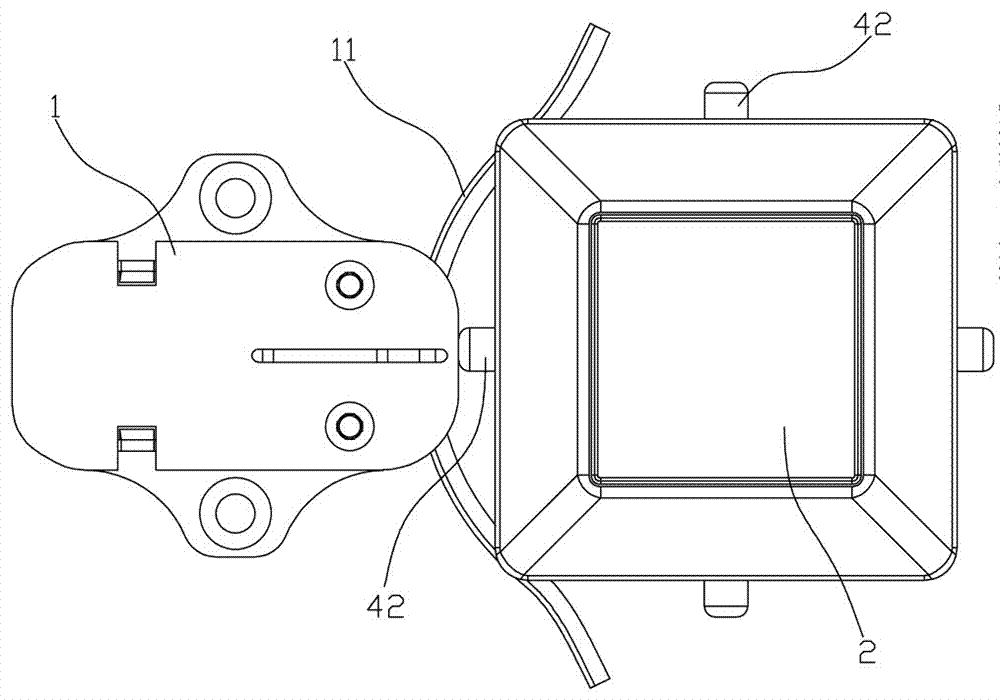
[0018] Such as figure 1 , figure 2 and image 3 As shown, the embodiment of the present invention provides an intelligent lock, comprising a motor assembly 1, a handle 2, a handle shaft 3 and a handle core 4 of a hollow structure, the handle core 4 is fixed on the handle 2, and the handle The shaft 3 is rotatably plugged into the inner ring of the handle core 4. The handle core 4 is provided with a plurality of first clutch pin holes 41 that run through the inner and outer surfaces of the handle core 4. The first clutch pin holes 41 are respectively provided with The...


PUM


Abstract

Provided is an intelligent lock. A lever handle shaft of the intelligent lock is rotatably inserted and connected in an inner ring of a lever handle core, multiple first clutching plug pin holes penetrating through the inner surface and the outer surface of the intelligent lock core are formed in the lever handle core, clutching plug pins and clutching plug pin springs sleeving the clutching plug pins are respectively arranged in the first clutching plug pin holes, one end of each clutching plug pin extends out of the outer surface of the lever handle core, a first counter-locking shifting block hole is formed in the inner surface of the lever handle core between every two adjacent first plug pin holes, reset springs and counter-locking shifting blocks arranged on the reset springs and extending out of the inner surface of the lever handle core are arranged in the first counter-locking shifting block holes, multiple second clutching plug pin holes are sequentially formed in the circumferential face of the end, in inserted connection with the inner ring of the lever handle core, of the lever handle shaft at intervals, and a second counter-locking shifting block hole is formed between every two adjacent second plug pin holes. A motor module comprises a motor and a clutching plug pin push plate moving with the motor to be in butting connection with the clutching plug pins and to push the other end of each clutching plug pin to extend out of the corresponding first clutching plug pin holes and extend into the second clutching plug pin holes.

Description

technical field [0001] The invention relates to the technical field of electronic intelligent locks, in particular to an intelligent lock. Background technique [0002] At present, most of the locks on the anti-theft door are locked and unlocked by the key, and some are locked by lifting the outer handle upwards by hand. When opening the door, use the key to rotate the center wheel of the lock cylinder several times to unlock. This method is mechanical locking. And unblanking, the problem that mechanical lock exists is: its mechanical key is easy to be duplicated, thereby safety is very poor. With the development of electronic technology, anti-theft locks are also developing in the direction of smart locks. The so-called smart locks refer to locks that are different from traditional mechanical locks and are more intelligent in terms of user identification, security, and management. For example, fingerprint locks are a kind of Human fingerprints are intelligent locks for ide...

Claims


Application Information

Patent Timeline
Patent Type & Authority Patents(China)
IPC IPC(8): E05B47/00G07C9/00
Inventor 谢庆文
Owner 谢庆文
Why Eureka
Try Eureka