Pneumatic tire
A pneumatic tire, tire circumferential technology, applied in tire parts, tire tread/tread pattern, transportation and packaging, etc., can solve the problem of difficulty in maintaining the rigidity level of the tread portion, reducing the rigidity of the tread portion, etc. The effect of braking performance on ice and improving driving stability on snow
- Summary
- Abstract
- Description
- Claims
- Application Information
AI Technical Summary
Problems solved by technology
Method used
Image

Examples
no. 1 approach
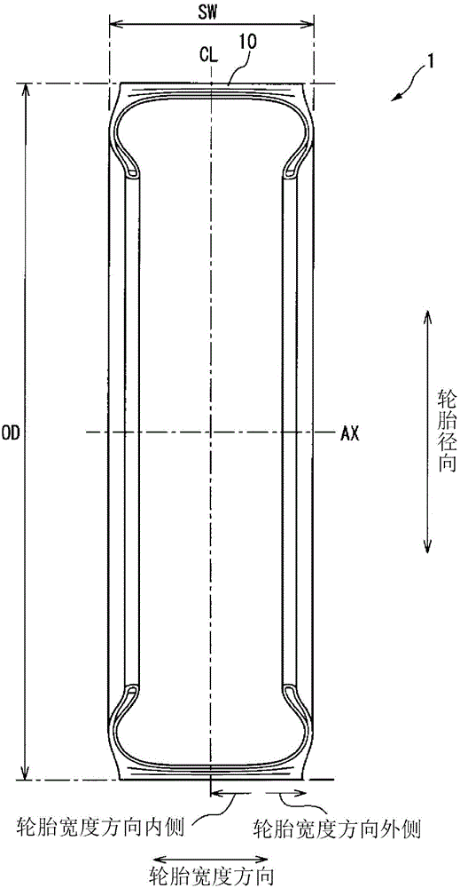
[0026] Hereinafter, a pneumatic tire 1 according to a first embodiment of the present invention will be described with reference to the drawings. figure 1 It is a meridian sectional view of the pneumatic tire 1 according to the first embodiment of the present invention. In addition, the meridian cross-sectional shape of the pneumatic tire 1 according to the first embodiment is the same as that of a conventional pneumatic tire. Here, the meridian cross-sectional shape of the pneumatic tire refers to the cross-sectional shape of the pneumatic tire appearing on a plane perpendicular to the tire equatorial plane CL.
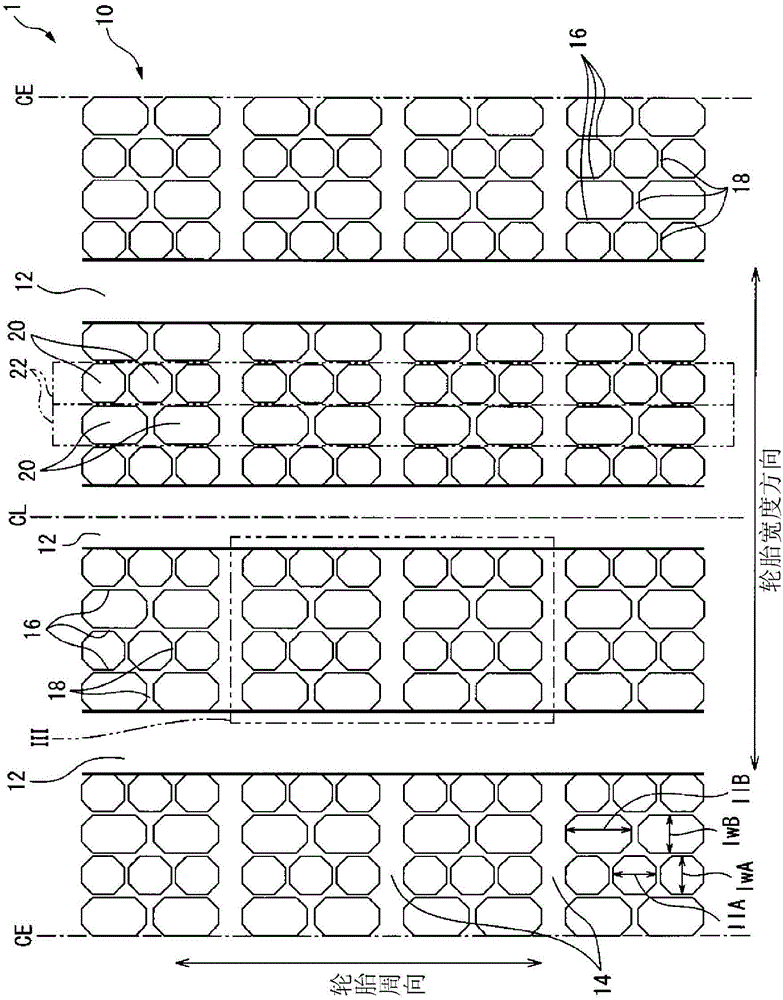
[0027] In the following description, the tire radial direction refers to a direction perpendicular to the rotation axis AX of the pneumatic tire 1 . The tire circumferential direction refers to the direction that rotates around the above-mentioned rotation axis AX (see figure 2 ). In addition, the tire width direction refers to a direction parallel to the above-m...
no. 2 approach
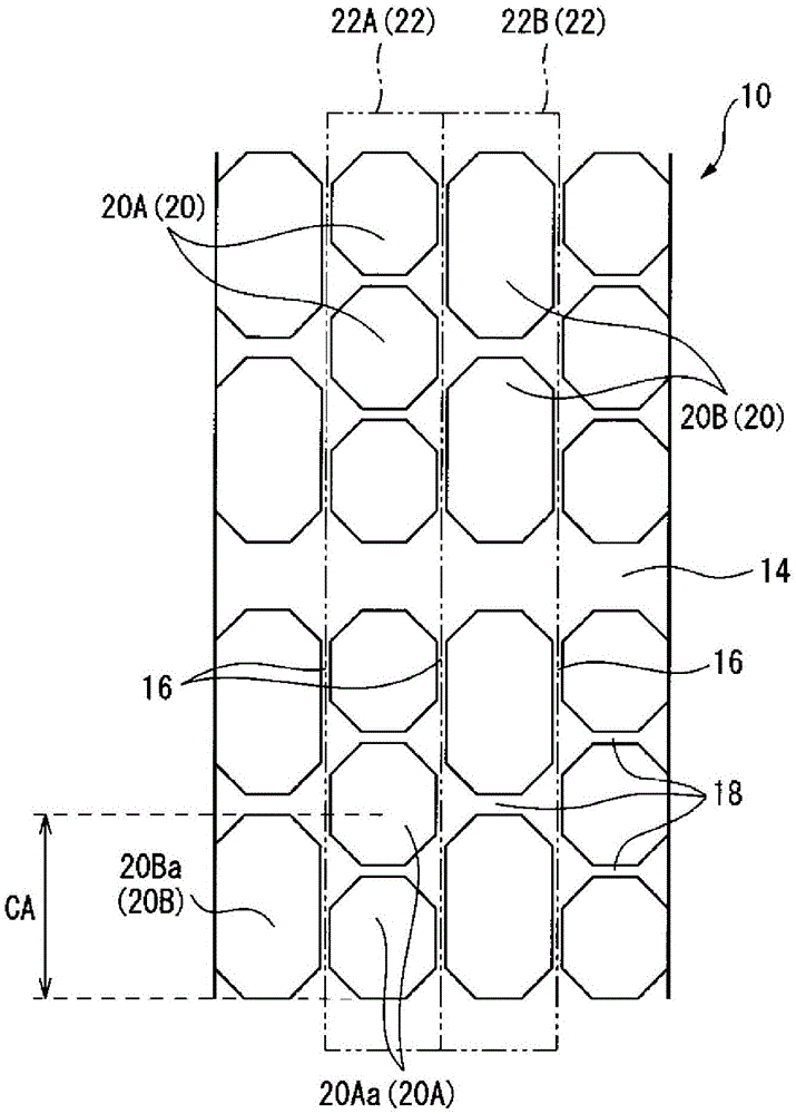
[0050] Below, refer to Figure 4 , the pneumatic tire 1 according to the second embodiment of the present invention will be described. Figure 4 It is a schematic development plan view showing a part of the tread portion 10 of the pneumatic tire 1 according to the second embodiment of the present invention. In addition, regarding the second embodiment, only the points of difference from the first embodiment will be described.
[0051] Such as Figure 4 As shown, in the pneumatic tire 1 according to the second embodiment, like the pneumatic tire 1 according to the first embodiment, lug grooves 14 are provided to communicate the circumferential main grooves 12 with each other or connect the circumferential main grooves 12 to the ground. Terminal CE is connected. Here, in the pneumatic tire 1 according to the first embodiment, the distance between lug grooves 14 adjacent in the tire circumferential direction is constant. On the other hand, in the pneumatic tire 1 according to...
no. 3 approach
[0057] Below, refer to Figure 5 , the pneumatic tire 1 according to the third embodiment of the present invention will be described. Figure 5 It is a schematic development plan view showing a part of the tread portion 10 of the pneumatic tire 1 according to the third embodiment of the present invention. In addition, regarding the third embodiment, only the points of difference from the first embodiment will be described. The pneumatic tire 1 according to the third embodiment is different from the pneumatic tire 1 according to the first embodiment in that the shape of the small blocks 20 is an arrow-feather shape directed toward the tire circumferential direction.
[0058] In the pneumatic tire 1 according to the third embodiment, as Figure 5As shown, the small block 20 has a convex portion 20P on one side in the tire circumferential direction that is convex toward the small block adjacent in the tire circumferential direction, and has a convex portion 20P on the other sid...
PUM
 Abstract
Description
Claims
Application Information