Safe photovoltaic system

A technology for photovoltaic equipment and equipment status, applied in photovoltaic modules, photovoltaic power generation, photovoltaic system monitoring, etc.

Active Publication Date: 2015-11-18
PHOENIX CONTACT GMBH & CO KG
View PDF9 Cites 55 Cited by
  • Summary
  • Abstract
  • Description
  • Claims
  • Application Information

AI Technical Summary

Problems solved by technology

However, such solutions are mostly only for one-time emergency cut-off

Method used


Image

  • Safe photovoltaic system
  • Safe photovoltaic system
  • Safe photovoltaic system

Examples


Embodiment Construction

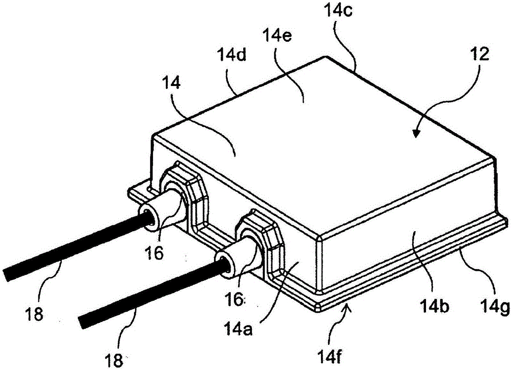
[0136] figure 1 A solar junction box 12 is shown with a junction box housing 14 for mounting on the rear side of the solar module. The dielectric terminal box housing 14 is designed in the form of a cover and includes surrounding side walls 14 a to 14 d and a cover 14 e. In the junction box housing 14 of the figure 1 An opening is provided on the lower side 14 f , which is not visible in the center, through which the conductor strips exiting the solar module enter the solar junction box 12 for contacting there. The junction box housing 14 has two cable feedthroughs 16 on one of the side walls 14a, through which the line conductors 18 are guided into the solar junction box 12 and connected to the junction box housing 14. The interior is connected, for example by means of contact terminals, not shown, in order to dissipate the electrical power generated by the solar module. The edge 14g is used to glue the solar junction box to the solar module. For the basic construction of...


PUM


Abstract

The invention provides a fault detection system in a photovoltaic system (1), which uses a first measurement characteristic curve and optionally a second measurement characteristic curve to record the system status, and can thus distinguish malfunctions from the normal system operating state.

Description

technical field [0001] The invention relates to a method for identifying electrical faults in photovoltaic installations, and to a system comprising solar modules connected to each other in at least one series connection and a system for disconnecting solar modules individually and for disconnecting solar The module is safely reconnected to the photovoltaic device on the line. Background technique [0002] To date, solar installations have often been equipped without special safety precautions. A solar junction box (also called junction box or combiner box) present in each solar module is mainly used to receive the mechanical terminals of the conductor ribbons (also called ribbon) of the solar module and its bypass diodes. Such simple solar modules provide voltage once illuminated. [0003] Typically, solar modules are connected in series with one another in so-called lines (also called strings) in order to achieve high line voltages. This voltage of solar modules connect...

Claims


Application Information

Patent Timeline
Patent Type & Authority Applications(China)
IPC IPC(8): H02H7/20H02H11/00H02S50/10
CPCH02H7/20H01L31/02021H02H11/00H02S50/10G01R31/52G01R31/54H02S50/00Y02E10/50H02H3/08H02H3/20H02H7/268
Inventor W·霍夫特
Owner PHOENIX CONTACT GMBH & CO KG
Why Eureka
Try Eureka