Helicopter engine start control circuit

A technology for engine start and start control, which is applied to aircraft power units, aircraft parts, transportation and packaging, etc., and can solve problems such as the safety impact of helicopters

Active Publication Date: 2017-06-06
HARBIN
View PDF5 Cites 0 Cited by
  • Summary
  • Abstract
  • Description
  • Claims
  • Application Information

AI Technical Summary

Problems solved by technology

[0005] Its disadvantage is: under normal circumstances, when the engine is started or the engine is running cold, the driver is required to release the rotor brake. If the driver forgets to release the rotor brake due to driver error, it will affect the safety of the helicopter.

Method used


Image

  • Helicopter engine start control circuit
  • Helicopter engine start control circuit

Examples


Embodiment Construction

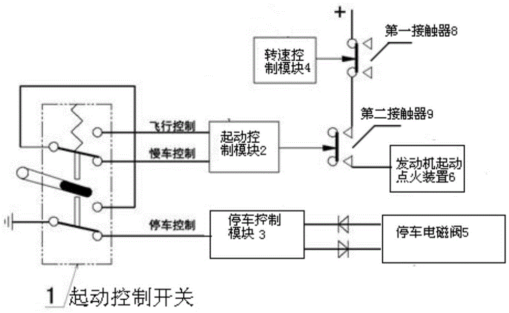
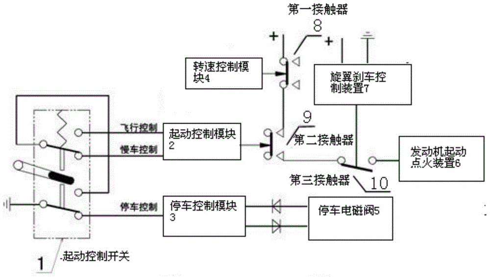
[0020] The present invention will be described in further detail below. see figure 2 ,

[0021] Helicopter engine starting control circuit, including a starting control switch 1, a starting control module 2, a parking control module 3, a speed control module 4, a parking solenoid valve 5, an engine starting ignition device 6, and a rotor brake control device 7, wherein the starting control switch 1 The parking control terminal of the parking control module 3 is connected to the input terminal of the parking control module 3, the parking control module 3 is connected to the parking solenoid valve 5 through a diode, the flight control terminal and the idle control terminal of the starting control switch 1 are connected to the input terminal of the engine starting control module 2, and the starting control The module 2 is connected to the control end of the second contactor 9, the speed control module 4 is connected to the control end of the first contactor 8, the rotor brake c...


PUM


Abstract

The invention belongs to the helicopter avionics design technical field, and especially relates to an engine starting control circuit; a starting circuit is added with a rotor brake control device; the control circuit can control a starting state of the engine; so when driver maloperation causes the rotor brake to be in a brake state, the driver cannot start up the engine.

Description

technical field [0001] The invention belongs to the technical field of helicopter avionics design, in particular to an engine start control circuit. Background technique [0002] The current helicopter engine start control circuit can be found in figure 1 , which includes a starting control switch 1, a starting control module 2, a parking control module 3, a speed control module 4, a parking solenoid valve 5, an engine starting ignition device 6, and a rotor brake control device 7, wherein the parking control terminal of the starting control switch 1 It is connected to the input terminal of the parking control module 3, the parking control module 3 is connected to the parking solenoid valve 5 through a diode, the flight control terminal and the idle control terminal of the starting control switch 1 are connected to the input terminal of the engine starting control module 2, and the starting control module 2 is connected to the first The control terminals of the two contacto...

Claims


Application Information

Patent Timeline
Patent Type & Authority Patents(China)
IPC IPC(8): B64D31/06
Inventor 李昊晗檀婧杰马彦鹏李存杨春宝
Owner HARBIN
Why Eureka
Try Eureka