A device and method for pulling out coiled tubing under pressure
What is AI technical title?
AI technical title is built by Patsnap AI team. It summarizes the technical point description of the patent document.
A process method and tubing technology, which is applied in the field of coiled tubing device with pressure pulling out, can solve the problems of reservoir damage, manpower and material resources, etc., and achieve the effect of avoiding injury and high-efficiency pulling out.
Active Publication Date: 2017-08-04
PETROCHINA CO LTD
View PDF7 Cites 0 Cited by
Summary
Abstract
Description
Claims
Application Information
AI Technical Summary
This helps you quickly interpret patents by identifying the three key elements:
Problems solved by technology
Method used
Benefits of technology
Problems solved by technology
At present, we can learn from the process of killing the well and pulling the tubing. After the well is killed, the coiled tubing is pulled out, but the well killing operation will cause great damage to the reservoir and consume a lot of manpower and material resources.
Method used
Image
Click on the blue label to locate the original text in one second.
Reading with bidirectional positioning of images and text.
Examples
Embodiment 1
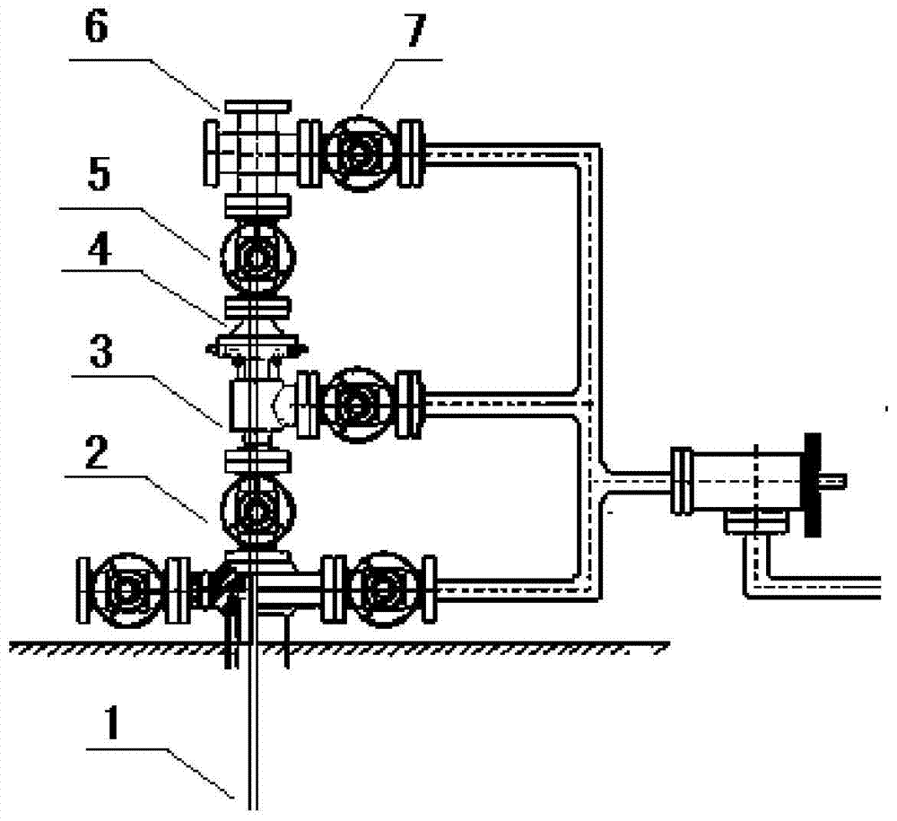
[0032] Embodiment 1: a kind of coiled tubing device with pressure, such as figure 1 As shown, the lower end of the coiled tubing 1 goes down into the wellbore, the upper end of the coiled tubing 1 passes through the main control valve 2 and the first reducing flange 4, and is suspended on the hanger 3, and the main control valve 2 is connected to the hanger 3, The other end of the hanger 3 is connected to the first reducing flange 4, the other end of the first reducing flange 4 is connected to the gate valve 5, the other end of the gate valve 5 is connected to the small cross 6, and the other end of the small cross 6 is connected to the gate valve 7 ,
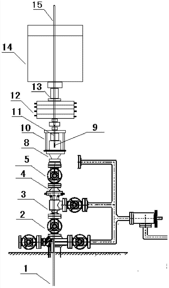
[0033] like figure 2 As shown, the lower end of the coiled tubing 1 goes down into the wellbore, the upper end of the coiled tubing 1 passes through the main control valve 2 and the reducing flange 4, and is suspended on the hanger 3, the main control valve 2 is connected with the hanger 3, and the hanger 3 The other end of ...
Embodiment 2
[0036] Embodiment 2: a kind of method that is used for the coiled tubing in the gas well that is pulled out under pressure, such as figure 1 , figure 2 , image 3, Figure 4 as shown,
[0037] 1. Insert the plug in the pipe;
[0038] (1) Close the gate valve 5, and remove the upper gas tree, that is, the small cross 6 and the gate valve 7.
[0039] (2) Using explosion-proof tools, install the second reducing flange 8, the operation window 10, the four-ram BOP 12, the BOP box 13, and the injection head 14 on the upper part of the gas tree gate valve 5 in sequence.
[0040] (3) Connect the first running tool 11 and the second running tool 15 , and then pass them through the injection head 14 , the blowout prevention box 13 , the four-ram blowout preventer 12 , and the operation window 10 . Open the operation window 10, and connect the connected first feeding tool 11 and the second feeding tool 15 with the in-line plug 9 at the inner cylinder thereof.
[0041] (4) Seal the...
PUM
Abstract
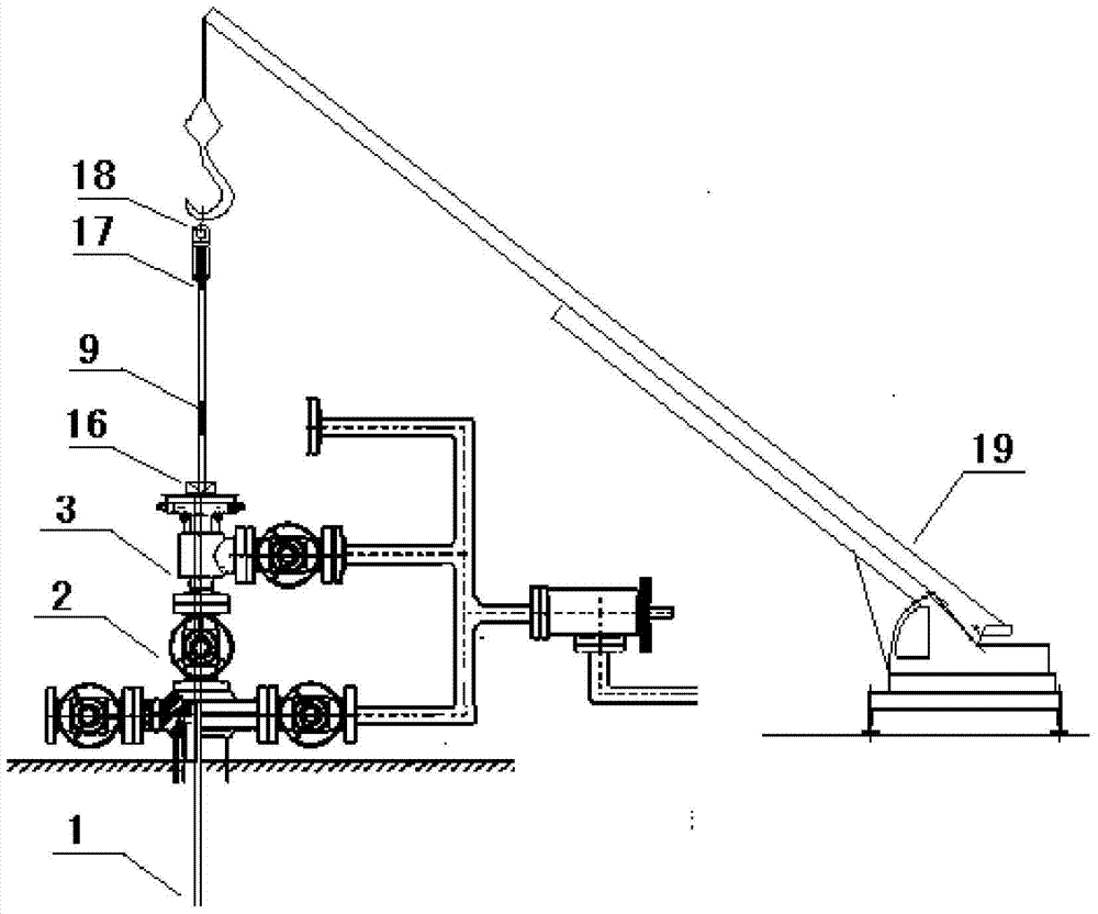
The invention relates to a coiled tubing device and a process method for pulling out under pressure, and belongs to the technical field of gas field exploitation. The method includes: using the injection head on the coiled tubing machine to clamp the connecting body of the feeding tool and the in-pipe plug, driving the in-pipe plug into the inside of the coiled tubing; lifting the feeding tool on the injection head to make the in-pipe plug sit Sealing, the injection head increases the lifting force to separate the plug in the tube from the feeding tool, the plug in the tube stays inside the coiled tubing, and seals the coiled tubing; penetrates the mandrel at the end of the coiled tubing, and installs the outer puller At the end of the coiled tubing, use a crane to lift the coiled tubing on the outer slip puller, so that the slips hanging from the coiled tubing are released; reversely pass the pulled out coiled tubing through the operation window, blowout preventer, injection head and other equipment in sequence, Then use the injection head to continue to lift the coiled tubing, and at the same time wrap the continuously pulled out tube into the drum on the coiled tubing machine.
Description
technical field [0001] The invention relates to a device and a process method for pulling out a coiled tubing under pressure, belonging to the technical field of gas field exploitation. Background technique [0002] As the production time of the gas well continues, the production capacity of the gas well gradually decreases. When the flow rate of the gas well is lower than the critical liquid-carrying flow rate, the bottom of the well begins to accumulate liquid. If the liquid drainage measures are not taken in time, the gas well may be flooded and stop production. Based on the theory of wellbore two-phase flow and minimum liquid-carrying flow rate, a small-diameter coiled tubing is run into the original wellbore as a production string, and after the coiled tubing is cut off, it is suspended at the gas production wellhead by a special hanger. This technology can be used to a certain extent Reduce the critical liquid-carrying velocity of the gas well and increase the gas velo...
Claims
Application Information
Patent Timeline
Application Date:The date an application was filed.
Publication Date:The date a patent or application was officially published.
First Publication Date:The earliest publication date of a patent with the same application number.
Issue Date:Publication date of the patent grant document.
PCT Entry Date:The Entry date of PCT National Phase.
Estimated Expiry Date:The statutory expiry date of a patent right according to the Patent Law, and it is the longest term of protection that the patent right can achieve without the termination of the patent right due to other reasons(Term extension factor has been taken into account ).
Invalid Date:Actual expiry date is based on effective date or publication date of legal transaction data of invalid patent.

