Multi-point switching apparatus

A switching device and multi-point technology, applied in the direction of contacts, tapped fixed resistor devices, contact engagement, etc., can solve difficult problems and achieve the effect of improving the machining accuracy of parts

Inactive Publication Date: 2015-11-25
ALPS ALPINE CO LTD
View PDF4 Cites 2 Cited by
  • Summary
  • Abstract
  • Description
  • Claims
  • Application Information

AI Technical Summary

Problems solved by technology

In addition, even if the gap between the patterns on the switching side can be reduced by improving the machining accuracy of parts, there is still a problem that it is difficult to stably realize the switching operation of continuous conduction every time it is operated.

Method used


Image

  • Multi-point switching apparatus
  • Multi-point switching apparatus
  • Multi-point switching apparatus

Examples


no. 1 Embodiment approach

[0031] Hereinafter, embodiments of the present invention will be described in detail using the drawings. In addition, for the sake of easy understanding, dimensions are appropriately changed with respect to the drawings.

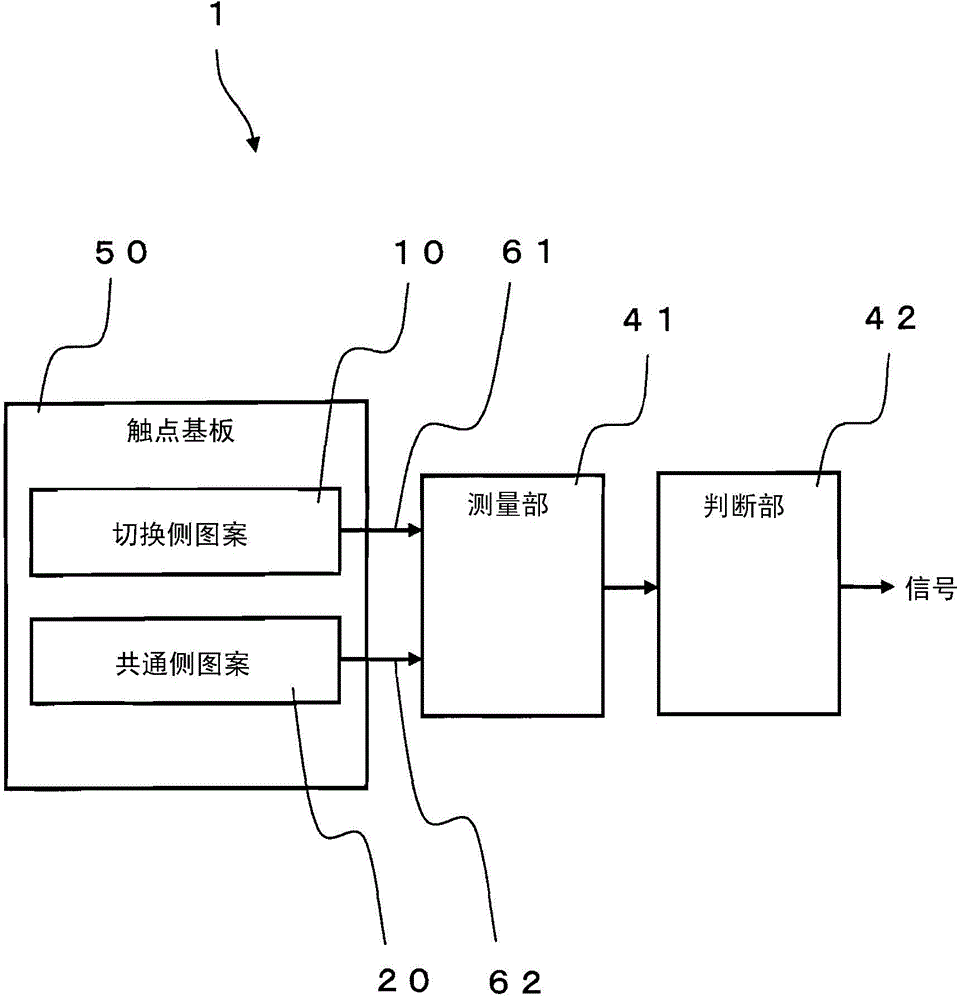
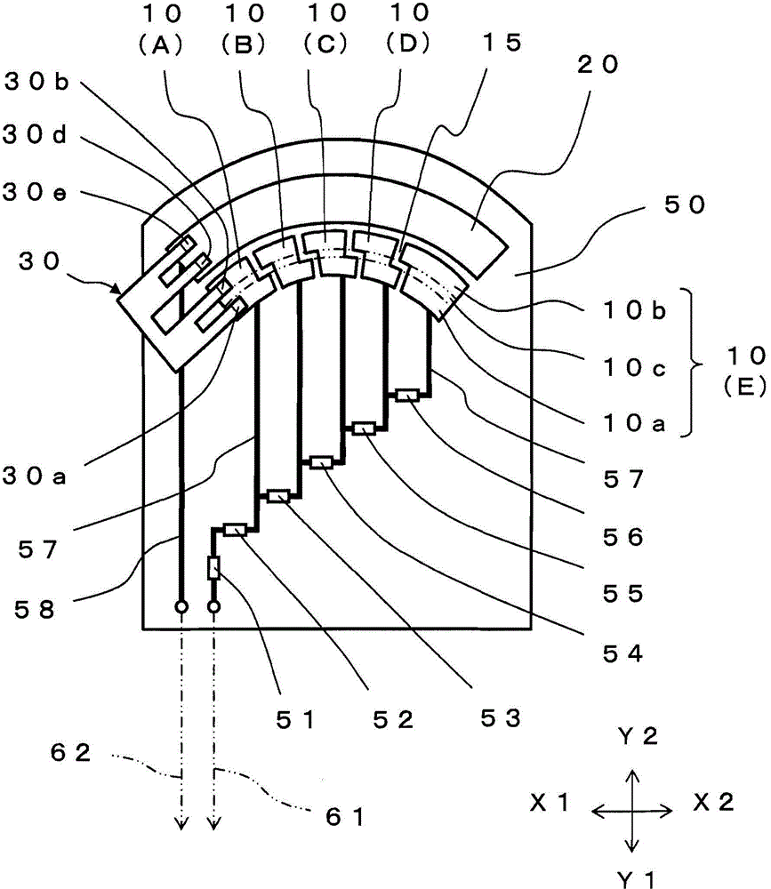
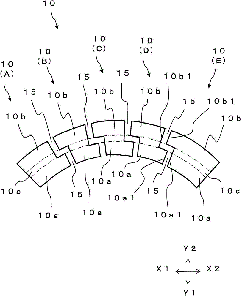
[0032] figure 1 It is a block diagram showing the multipoint switching device 1 according to the embodiment of the present invention. figure 2 is a schematic diagram showing the contact substrate 50 and the slider 30 . image 3 is a schematic diagram showing switching side patterns. Figure 4 is an outline view showing the slider 30, Figure 4 (a) is a floor plan, Figure 4 (b) is a front view. Figure 5 It is a schematic diagram which shows the example of the movement position of the slider 30. Image 6 It is a graph showing the measured value measured by the measuring section.

[0033] like figure 1 As shown, the multi-point switching device 1 of this embodiment includes a contact substrate 50 , a measurement unit 41 connected to the switching s...


PUM


Abstract

A multi-point switching apparatus includes a continuous common pattern formed on a contact circuit board, equally spaced to-be-switched patterns, and a slider that is brought into sliding contact with both the common pattern and one to-be-switched pattern. The slider is moved to make a switchover in succession. The slider includes a first sliding part and second sliding part that are elastically deformable individually. Each to-be-switched pattern includes a first pattern part placed so as to be brought into sliding contact with the first sliding part and a second pattern part placed so as to be brought into sliding contact with the second sliding part. The first pattern part and second pattern part are electrically connected to each other for each of the to-be-switched patterns. While any of the first sliding part and second sliding part is in a space, the other is in sliding contact with the to-be-switched pattern.

Description

technical field [0001] The present invention relates to a multi-point switching device capable of stably performing a switching operation of continuous conduction. Background technique [0002] A multi-point switching device that selectively conducts a slider to one of a plurality of switching side patterns is used in various fields. For example, Patent Document 1 discloses a multipoint input switcher suitable for switching input signals. [0003] Figure 9 It is a schematic diagram of the conventional switch 100 described in patent document 1. Figure 10 It is a schematic diagram of the multi-point input switcher 200 described in patent document 1. [0004] In the conventional switch 100, a continuous common-side pattern 122 and a plurality of intermittently-shaped switching patterns 123 are formed in parallel on a substrate. 123 brushes (sliders) 124 in common sliding contact. By moving the brush 124 to conduct one of the plurality of switching side patterns 123 , the ...

Claims


Application Information

Patent Timeline
Patent Type & Authority Applications(China)
IPC IPC(8): H01H19/10H01H19/14H01H19/58
CPCH01H19/10H01H19/14H01H19/585H01C10/36H01C10/48H01H1/365H01H1/44H01H15/005H01H15/10
Inventor 菊地刚
Owner ALPS ALPINE CO LTD
Why Eureka
Try Eureka