
Parking brake control system and control method for locomotive

A parking brake and control method technology, applied in the direction of brakes, brake transmission devices, vehicle components, etc., can solve problems such as easy misoperation, abnormal parking of locomotives, etc., to improve safety, prevent misapplied actions, and prevent misuse The effect of mitigating actions

Active Publication Date: 2015-12-02
CRRC ZIYANG CO LTD
View PDF7 Cites 19 Cited by
  • Summary
  • Abstract
  • Description
  • Claims
  • Application Information

AI Technical Summary

Problems solved by technology

During the normal operation of the locomotive, the parking brake is prone to malfunction, resulting in abnormal parking of the locomotive

Method used


Image

  • Parking brake control system and control method for locomotive

Examples


Embodiment Construction

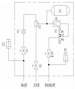
[0023] like figure 1 Shown, the present invention comprises MCU, interlocking pressure switch, former parking braking device (existing parking braking device).

[0024] The MCU is used to receive the opening signal or closing signal transmitted by the pressure switch, and allow the implementation of parking braking or parking braking relief according to the received signal;

[0025] The interlock pressure switch is figure 1 A12 in A12 is used to detect the pressure of the brake pipe, and send an open signal or a close signal to the MCU to realize the interlock control of the parking brake and the pressure of the brake pipe. The action range is 300~400kPa.

[0026] The original parking brake includes figure 1 A1~A9 in the figure are respectively the first cut-off plug, shrinkage cavity, two-way valve, second cut-off plug, air cylinder, pressure reducing valve, double electric control solenoid valve, electric interlock plug, and pressure switch. Among them, The first cut-off...


PUM


Abstract

The invention provides a parking brake interconnected control system for a locomotive, which comprises an original parking brake device, a microprogrammed control unit (MCU) and an interconnected pressure switch connected to a brake pipe, wherein the MCU is used for receiving a cut-off signal or a closing signal transmitted by the pressure switch and allowing implementation of parking brake or release of parking brake according to the received signal; and the interconnected pressure switch is used for detecting the magnitude of the pressure of the brake pipe and transmitting the cut-off signal or the closing signal to the MCU so as to realize interconnected control of the parking brake and the pressure of the brake pipe. The system provided by the invention realizes the interconnection of use of the parking brake and the pressure of the brake pipe; in normal operation of the locomotive, the parking brake can not be applied, so that the mistakenly applied action of the parking brake is avoided; and before release of the parking brake, release of air brake needs to be carried out in advance, so that the mistakenly released action of the parking brake is avoided and the safety of the parking brake is improved.

Description

technical field [0001] The invention belongs to the technical field of locomotive brake control, and in particular relates to a parking brake control system for a locomotive and a control method thereof. Background technique [0002] The existing locomotive parking brake control is usually controlled separately from the locomotive braking system, and the parking brake can be applied and released at any time. During the normal operation of the locomotive, the parking brake is prone to malfunction, resulting in abnormal parking of the locomotive. Contents of the invention [0003] In order to solve the above problems, the present invention provides a parking brake interlock control system for locomotives, including the original parking brake device, which includes a first cut-off plug, a shrinkage hole, a two-way valve, a second cut-off Plug door, air cylinder, pressure reducing valve, double electric control solenoid valve, electric interlock plug door, pressure switch, th...

Claims


Application Information

Patent Timeline
Patent Type & Authority Applications(China)
IPC IPC(8): B60T13/36B60T13/68
CPCB60T13/365B60T13/683
Inventor 姜葛何明洋张斌孙川
Owner CRRC ZIYANG CO LTD
Learn More