a vacuum relay

A technology of vacuum relay and vacuum chamber, which is used in high-voltage air circuit breakers, circuits, electrical switches, etc., to achieve the effect of improving continuous disconnection performance, facilitating the rapid disappearance of arcs, and ensuring vacuum purity

Inactive Publication Date: 2018-10-30
南存赞
View PDF5 Cites 0 Cited by
  • Summary
  • Abstract
  • Description
  • Claims
  • Application Information

AI Technical Summary

Problems solved by technology

[0003] The purpose of the present invention is to provide a vacuum relay to solve the problem that the existing vacuum relay cannot produce arc extinguishing effect well

Method used


Image

  • a vacuum relay
  • a vacuum relay
  • a vacuum relay

Examples


Embodiment 1

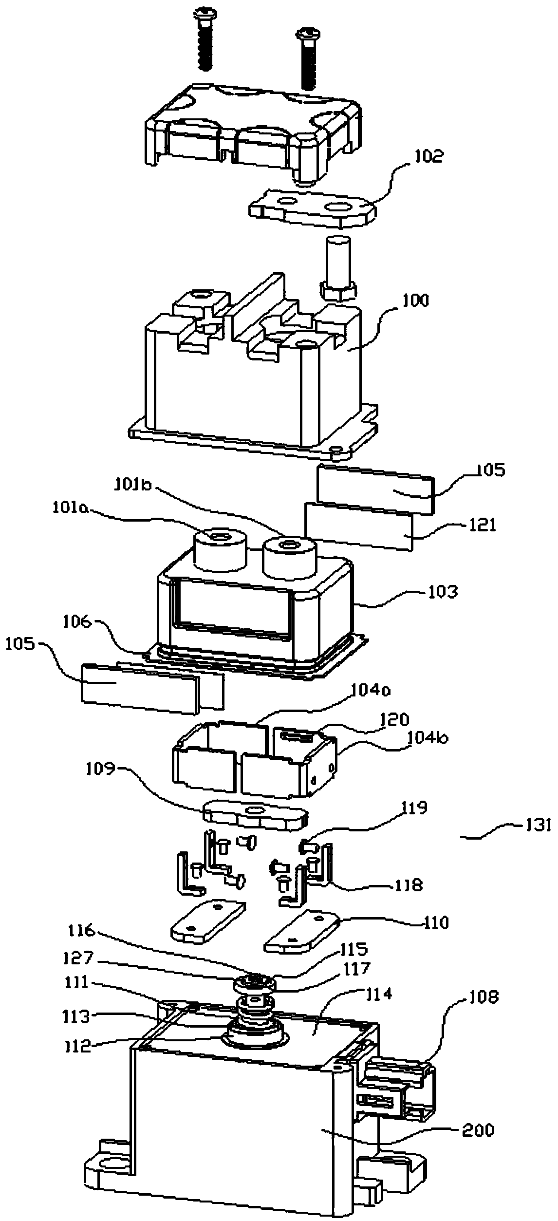
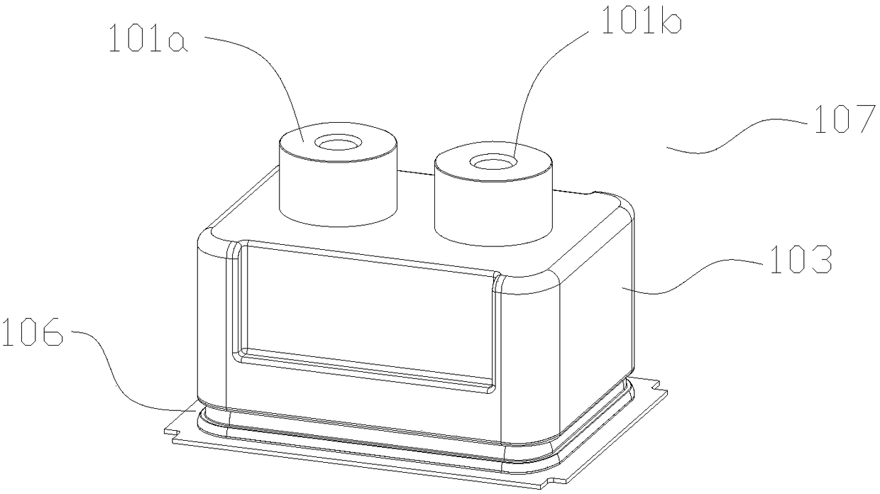
[0035] Figure 1, figure 2 As shown, the vacuum relay provided in this embodiment includes an upper cover 100, static contacts 101a, 101b, a ceramic housing 103, an arc extinguishing mechanism 131, a magnet 105, a base 200, an external connecting insert 108, a moving contact 109, and a base 200 An upper yoke 114 is provided on it. Wherein, the ceramic shell 103 is provided with a connecting member 106, and the upper yoke 114 is provided with a through hole, and the upper yoke around the through hole is fixedly connected with an iron core sleeve 205, and the iron core sleeve 205 is located on the upper yoke 114. Below, the ceramic shell 103 is located above the upper yoke 114 . The ceramic shell 103 and the upper yoke 114 are fixedly connected by the connecting member 106 , so that the ceramic shell 103 , the upper yoke 114 and the core sleeve 205 form a sealed vacuum cavity. The ceramic shell 103 and the upper yoke 114 form a ceramic cavity 107 , and the ceramic cavity 107 i...

Embodiment 2

[0045] Except for the following parts of the vacuum relay provided in this embodiment are different from Embodiment 1, the implementation of the remaining parts is the same as that of Embodiment 1. The details of this embodiment are as follows:

[0046] Such as Figure 6A , 6B As shown, in this embodiment, the arc extinguishing mechanism 130 includes two arc extinguishing grid structures, and each arc extinguishing grid structure includes a set of п-shaped arc extinguishing sheets 123, and these п-shaped arc extinguishing sheets 123 are supported by metal materials . It is connected and fixed by connecting pieces to form an arc extinguishing grid structure. Wherein, the connecting piece is made of insulating metal material. Specifically, the connecting piece includes a connecting fixing rod 124, a washer 125 and a fixing nut 126, all of which are made of insulating processed metal materials. The connecting and fixing rods 124 sequentially pass through the connecting holes ...


PUM


Abstract

The invention provides a vacuum relay comprising a top cover and pedestal. A vacuum chamber containing a ceramic housing is disposed in the top cover. A movable contact, a static contact, and a driving shaft are arranged in the vacuum chamber. One end of the static contact is located in the vacuum chamber. The other end of the static contact passes through the vacuum chamber and the top cover to reach exterior. An arc-extinguishing mechanism is arranged around the movable contact and the static contact. A magnet is disposed on the outer side of the ceramic housing and magnetizes the arc-extinguishing mechanism through the ceramic housing in order that arc generated when the static contact and the movable contact are separated is released by the arc-extinguishing mechanism. Each of two arc-extinguishing grids of the arc-extinguishing mechanism includes more than one arc-extinguishing sheet. When one arc-extinguishing sheet is included, the arc can be elongated under the effect of magnetic field force in order to be easy to extinguish. When the arc-extinguishing grid include multiple arc-extinguishing sheets, long arc can be cut into a string of short arc so as to be easy to extinguish. An air exhaust bar is provided in order to further guarantee vacuum degree in the vacuum chamber, thereby enabling the arc to fast disappear and improving the continuous disconnected performance of a circuit.

Description

technical field [0001] The invention relates to the related technical field of vacuum relays, in particular to a vacuum relay. Background technique [0002] With the development of automation technology, in order to ensure the safety of electricity consumption and output power in various related fields, the requirements for switching voltage and switching current of relays are getting higher and higher. The traditional relay is limited by its own manufacturing technology, and its relay contacts are prone to bonding failure or continuous arc burning of the contact system to make it invalid. In order to solve the above problems, vacuum relays are generally used at present. However, the existing vacuum relays generally adopt the method of placing the magnet and the magnetic guide plate outside the ceramic shell, and because of the material, the arc extinguishing grid structure cannot be installed in the vacuum chamber, so that the magnetic field outside the ceramic shell acts ...

Claims


Application Information

Patent Timeline
Patent Type & Authority Patents(China)
IPC IPC(8): H01H33/664H01H9/44H01H9/34
CPCH01H9/34H01H9/44H01H33/664
Inventor 南存赞
Owner 南存赞
Why Eureka
Try Eureka