A system and method for improving energy transmission efficiency based on energy distribution characteristics

A technology of energy transmission efficiency and energy distribution, which is applied in the microwave field, can solve the problems of low RF to DC energy conversion efficiency, difficulty in obtaining rectification efficiency, and rectification circuits that do not achieve optimal efficiency.

Active Publication Date: 2017-08-29
XIAN INSTITUE OF SPACE RADIO TECH
View PDF4 Cites 0 Cited by
  • Summary
  • Abstract
  • Description
  • Claims
  • Application Information

AI Technical Summary

Problems solved by technology

in figure 2 (a) It is widely used in the energy receiving end of solar power plants. The receiving antenna and rectification form have the advantages of high power reception and easy array combination. However, due to more intermediate connections and more energy loss, the energy conversion efficiency from RF to DC Reduced, the transmission efficiency from DC to DC of the system can only reach less than 5% (the DC power supplied by the power supply to the microwave transmitter to the DC power output by the DC synthesis module, referred to as DC to DC)
figure 2 The form of the rectifying antenna shown in (b) has the advantages of compact structure, etc. However, because the uneven distribution of energy and other factors are not considered and the uniform receiving method is adopted, most of the rectifying circuits do not reach the optimal efficiency state, and the system DC to DC The transmission efficiency can only reach less than 10% (the DC power supplied by the power supply to the microwave transmitter to the DC power output by the DC synthesis module), so it is difficult to obtain the best rectification efficiency

Method used


Image

  • A system and method for improving energy transmission efficiency based on energy distribution characteristics
  • A system and method for improving energy transmission efficiency based on energy distribution characteristics
  • A system and method for improving energy transmission efficiency based on energy distribution characteristics

Examples


Embodiment Construction

[0072] The following provides a specific embodiment of a microwave wireless energy transmission system for research on microwave wireless energy transmission technology.

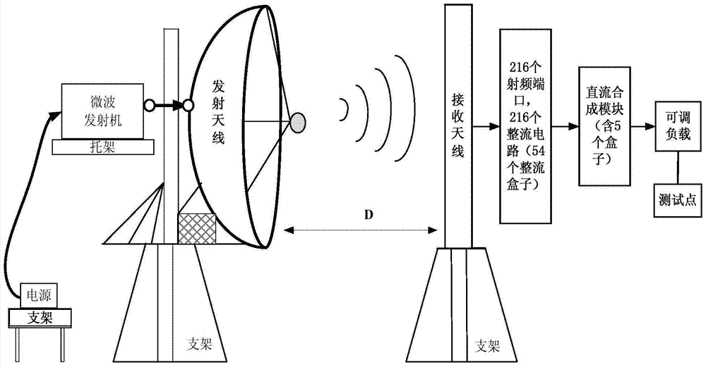
[0073] Such as figure 1 As shown, a system for improving energy transmission efficiency based on energy distribution characteristics, including: power supply, microwave transmitter, transmitting antenna, receiving antenna, rectifier circuit, and DC synthesis module;

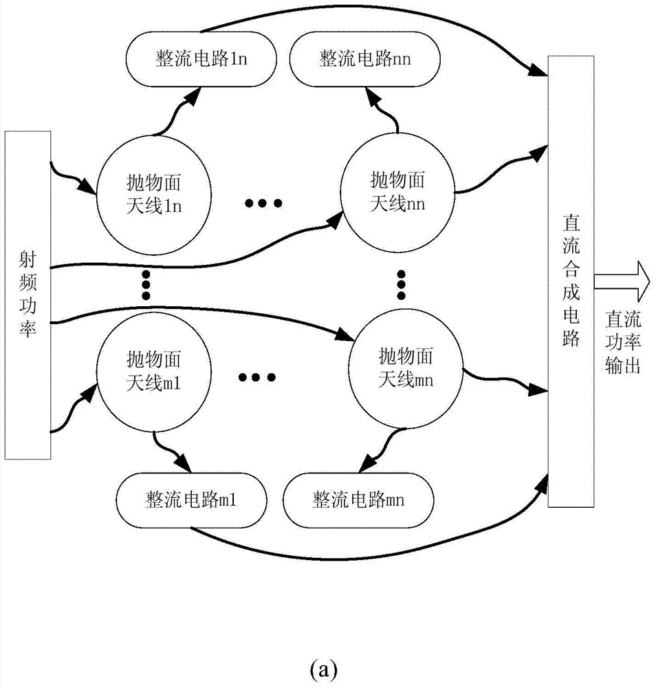
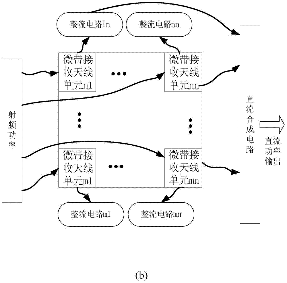
[0074] The receiving antenna includes a plurality of receiving antenna elements;

[0075] After the power supply supplies power to the microwave transmitter, the microwave transmitter generates radio frequency energy, forms a radio frequency signal and feeds it into the transmitting antenna, and transmits the radio frequency signal to the space through the transmitting antenna;

[0076] The aperture surface of the receiving antenna is divided into multiple sub-areas, and each sub-area is equipped with 4 receiving antenna units to receive radio...


PUM


Abstract

The invention discloses a system and a method for improving energy transmission efficiency based on energy distribution characteristics. Due to the non-uniformity of the energy distribution on the reception antenna end and the optimal matching state between the optimal efficiency and the input power of a rectification circuit , and on the basis of the energy distribution characteristics, various quantities of reception microstrip antenna units are adopted in various energy distribution areas to receive radio frequency signals and let the radio frequency signals to go into the rectification circuit directly or to go into the rectification circuit after power synthesis; the rectification circuit converts the radio frequency energy to DC energy after performing rectification processing on the radio frequency signal and lets the DC energy to go into a DC synthesis module; and the DC synthesis module obtains final output power after processing synthesis on the DC energy. The invention reduces connection loss between various members, realizes maximization reception of the radio frequency energy, finishes the maximization design of the rectification efficiency, and effectively improves the microwave wireless energy transmission efficiency of the system link.

Description

technical field [0001] The invention relates to a system and method for improving energy transmission efficiency based on energy distribution characteristics, and belongs to the field of microwave technology. Background technique [0002] In the research process of microwave wireless energy transmission technology between module spacecraft, energy transmission efficiency is a key index to measure the excellent performance of the system. The microwave wireless energy transmission system mainly includes three parts: microwave transmitting component, microwave receiving component and space transmission. The specific circuit is composed of four subsystems: microwave transmitter, microwave transmitting antenna, microwave receiving antenna and microwave rectifying circuit. The design scheme is as follows: figure 1 shown. [0003] The link efficiency of microwave wireless energy transmission system is mainly composed of three parts: DC to RF conversion efficiency, RF to DC convers...

Claims


Application Information

Patent Timeline
Patent Type & Authority Patents(China)
IPC IPC(8): H02J50/20
Inventor 马海虹栗曦朱正贤徐辉张波王毅杨林董亚洲
Owner XIAN INSTITUE OF SPACE RADIO TECH
Why Eureka
Try Eureka