Eureka AIR delivers breakthrough ideas for toughest innovation challenges, trusted by R&D personnel around the world.

Splicing device used for floor tiles and installing method thereof

A technology of splicing device and installation method, which is applied to floors, buildings, adhesives, etc., can solve the problems of affecting assembly, waste of manpower and material resources, and high transportation costs, and achieve the effect of convenient transportation and assembly, and easy disassembly.

Inactive Publication Date: 2015-12-09
蔡咏诗
View PDF5 Cites 5 Cited by
  • Summary
  • Abstract
  • Description
  • Claims
  • Application Information

AI Technical Summary

Problems solved by technology

[0002] In the prior art, in order to facilitate the quick installation and disassembly of the floor tiles, technicians designed the floor tile bracket for bonding with the floor tiles as a whole, and then passed the assembled floor tile unit through the edge provided at the edge of the floor tile bracket. Splicing together, this kind of operation method, because the upper and lower edges are integrated with the floor tile bracket, during the glue laying operation on the upper surface of the floor tile bracket, the glue will easily flow into the edge of the floor tile bracket In addition, due to the heavy weight of the floor tile itself, it is bonded with the floor tile bracket and then transported and sold, which makes the transportation cost higher and greatly wastes manpower and material resources

Method used


Image

  • Splicing device used for floor tiles and installing method thereof
  • Splicing device used for floor tiles and installing method thereof
  • Splicing device used for floor tiles and installing method thereof

Examples


Embodiment Construction

[0026] The technical solutions of the present invention will be further described below in conjunction with the accompanying drawings and through specific implementation methods.

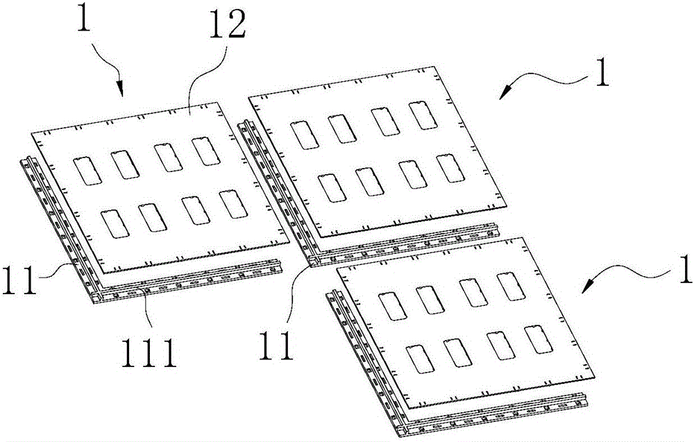
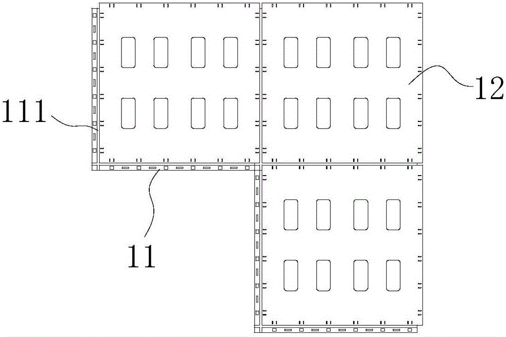
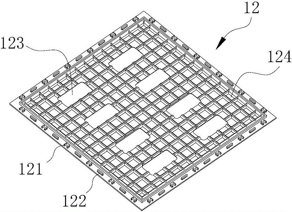
[0027] as attached Figure 1 to Figure 5 As shown, a splicing device for floor tiles includes several splicing units 1. The splicing unit 1 includes an L-shaped frame 11 and a floor tile fixing plate 12. The vertical and horizontal two straight arms of the L-shaped frame 11 The upper surface is respectively provided with barrier parts 111, and the barrier parts 111 are arranged in a cross, and the upper surfaces of the L-shaped skeleton 11 on both sides of the inner and outer sides of the barrier part 111 are respectively provided with inner card slots 112 and outer card slots 113, The inner hook 112 is engaged with the inner hooks 121 arranged on the adjacent two edges of the bottom surface of the floor tile fixing plate 12, and the outer hook 113 is fixed to the adjacent floor tiles of the splicin...


PUM


Abstract

The invention discloses a splicing device used for floor tiles and an installing method thereof. The splicing device comprises a plurality of splicing units. Each splicing unit comprises an L-shaped framework and a floor tile fixing plate. The upper surface of a longitudinal straight arm and the upper surface of a cross straight arm of each L-shaped framework are each provided with a blocking part. The blocking parts are arranged in a crossed intersection mode. The upper surfaces of the L-shaped frameworks on the inner sides and the outer sides of the blocking parts are provided with inner clamping grooves and outer clamping grooves. The inner clamping grooves are clamped to inner clamping hooks arranged on the edges of two adjacent sides of the lower bottom faces of the floor tile fixing plates, and the outer clamping grooves are clamped to outer clamping hooks arranged on the edges of one sides of the lower bottom faces of the floor tile fixing plates of the adjacent splicing units. Floor tiles adhere to the floor tile fixing plates on the spliced floor tile units, and then gaps between the adjacent floor tiles are flattened with gap beautifying glue. By means of the structural design, transportation and assembling are convenient, disassembling is convenient, the splicing device is convenient and fast to use, and producing and transporting cost can be effectively reduced.

Description

technical field [0001] The invention relates to the technical field of floor tiles, in particular to a splicing device for floor tiles and an installation method thereof. Background technique [0002] In the prior art, in order to facilitate the quick installation and disassembly of the floor tiles, technicians have designed the floor tile bracket for bonding with the floor tiles, and then the assembled floor tile unit is passed through the edge provided at the edge of the floor tile bracket. Splicing together, this kind of operation method, because the upper and lower edges are integrated with the floor tile bracket, during the glue laying operation on the upper surface of the floor tile bracket, the glue will easily flow into the edge of the floor tile bracket In addition, due to the heavy weight of the floor tile itself, it is bonded with the floor tile bracket and then transported and sold, which makes the transportation cost higher and greatly wastes manpower and materi...

Claims


Application Information

Patent Timeline
Patent Type & Authority Applications(China)
IPC IPC(8): E04F15/02
CPCE04F15/02194E04F15/087E04F2201/0146E04F15/02022E04F15/0215E04F15/08E04F2201/0138
Inventor 蔡詠诗蔡逸民
Owner 蔡咏诗
Why Eureka
Eureka Blog
Learn More