Multi-head polisher machine

A finishing machine, multi-head technology, applied in the field of multi-head finishing machines, can solve problems such as flatness damage

Inactive Publication Date: 2015-12-16
杨一舟
View PDF11 Cites 53 Cited by
  • Summary
  • Abstract
  • Description
  • Claims
  • Application Information

AI Technical Summary

Problems solved by technology

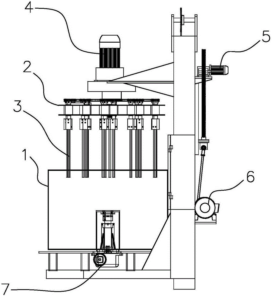
[0003] The technical problem to be solved by the present invention is: In order to solve the problem that the collision between the parts cannot be avoided when the current finishing machine finishes the surface of the parts, resulting in the destruction of the flatness, the present invention provides a multi-head finishing machine to solve the above problems

Method used


Image

  • Multi-head polisher machine
  • Multi-head polisher machine

Examples


Embodiment Construction

[0017] Embodiments of the present invention are described in detail below, examples of which are shown in the drawings, wherein the same or similar reference numerals designate the same or similar elements or elements having the same or similar functions throughout. The embodiments described below by referring to the figures are exemplary only for explaining the present invention and should not be construed as limiting the present invention. On the contrary, the embodiments of the present invention include all changes, modifications and equivalents coming within the spirit and scope of the appended claims.

[0018] In describing the present invention, it should be understood that the terms "center", "longitudinal", "transverse", "length", "width", "thickness", "upper", "lower", "front", " Back", "Left", "Right", "Vertical", "Horizontal", "Top", "Bottom", "Inner", "Outer", "Axial", "Radial", "Circumferential", etc. The indicated orientation or positional relationship is based ...


PUM


Abstract

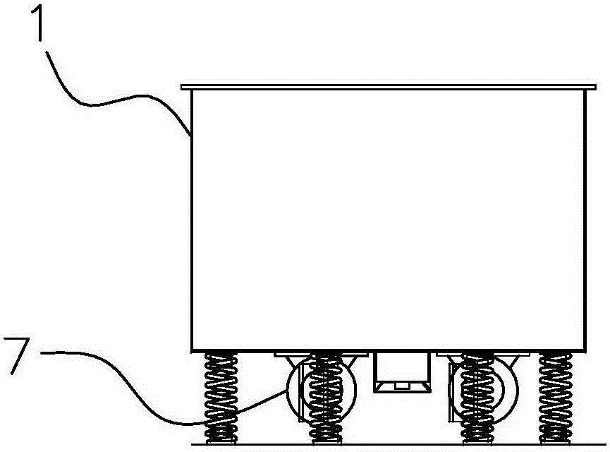
The invention provides a multi-head polisher machine. The multi-head polisher machine comprises a container, a rotating plate, a rotating mechanism, a lifting mechanism and a plurality of loading sticks. An opening is formed in the upper end of the container. The rotating plate is horizontally arranged over the container. The rotating mechanism comprises a first motor, a chain, a main chain wheel, a main shaft and a plurality of auxiliary chain wheels. The main shaft is fixed to the middle of the rotating plate. An output shaft of the first motor and the main shaft are coaxially fixed. The main shaft is sleeved with the main chain wheel. The loading sticks are sleeved with the auxiliary chain wheels respectively. The main chain wheel and the auxiliary chain wheels are linked through the chain. According to the multi-head polisher machine, parts are assembled on the loading sticks, the loading sticks are driven by the rotating plate to revolve, the loading sticks unceasingly rotate, and therefore the parts can rub abrasive materials in the container, and the mirror surface effect can be generated within a certain period of time when the abrasive materials make contact with the parts at a high speed. The surface flatness can not be damaged as long as the parts do not collide.

Description

technical field [0001] The invention relates to the technical field of parts surface processing equipment, in particular to a multi-head finishing machine. Background technique [0002] At present, the equipment used for finishing the surface of the parts is a finishing machine, including a swirling finishing machine and a vibrating finishing machine, and the abrasive is used to finish the surface of the parts in the working volume of the finishing machine; During polishing, parts and abrasives are mixed together, and the collision between parts will destroy the flatness of the surface. Therefore, it is difficult to achieve a mirror effect on the surface of hardware products by relying on the existing finishing machine. , It can only be polished by hand on a high-speed rotating cloth wheel, and the technical requirements of the manpower are very high. Non-skilled workers or polishers in different industries cannot polish the mirror effect. Contents of the invention [000...

Claims


Application Information

Patent Timeline
Patent Type & Authority Applications(China)
IPC IPC(8): B24B31/00B24B31/12B24B41/06
CPCB24B31/003B24B31/12B24B41/06
Inventor 杨一舟
Owner 杨一舟
Why Eureka
Try Eureka