Quick relay protection test vehicle

A technology of relay protection and test vehicle, applied in the direction of circuit breaker testing, etc., can solve the problems of troublesome winding and unwinding, untidy line arrangement, low efficiency of winding and unwinding, etc., and achieve the effect of improving efficiency and convenience.

Active Publication Date: 2015-12-16
STATE GRID CORP OF CHINA +1
View PDF9 Cites 2 Cited by
  • Summary
  • Abstract
  • Description
  • Claims
  • Application Information

AI Technical Summary

Problems solved by technology

[0008] This method is cumbersome to take up and pay off the wires, the arrangement of the wires is not neat, and the efficiency of the take-up and take-up is low

Method used


Image

  • Quick relay protection test vehicle
  • Quick relay protection test vehicle
  • Quick relay protection test vehicle

Examples


Embodiment 1

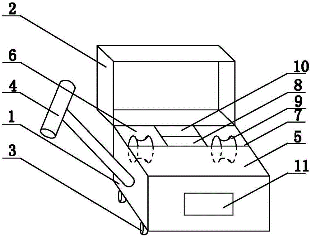
[0026] Embodiment 1: as figure 1 As shown, the relay protection rapid test vehicle of the present invention includes a vehicle body 1 and a device cover 2, a universal wheel 3 is respectively arranged at the four corners of the bottom of the vehicle body 1, and a pull rod 4 is provided on the side of the vehicle body 1. The body 1 is provided with a tester grid 5, a current test wire reel 6, a voltage test wire reel 7 and a power supply 8, and the current test wire reel 6 and the voltage test wire reel 7 are provided with a take-up and release roller 9, and the current A drive device 10 is arranged between the test wire reel 6 and the voltage test wire reel 7, the take-up and pay-off roller 9 is connected to the power output shaft of the drive device 10, the side of the car body 1 is provided with a control panel 11, and the drive device 10 is controlled by The panel 11 is connected to a power source 8 .

Embodiment 2

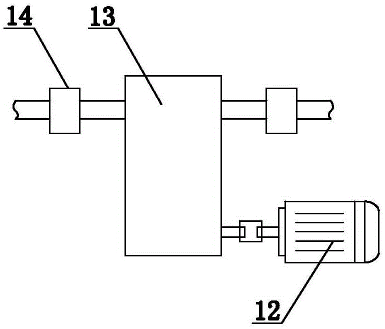
[0027] Embodiment 2: on the basis of the structure described in embodiment 1, as figure 2 As shown, the driving device 10 includes a motor 12, a dual output gearbox 13 and a clutch 14, the power end of the motor 12 is connected to the power supply 8 through the control panel 11, and the rotor of the motor 12 is connected to the power input end of the dual output gearbox 13 through a coupling , the two power output ends of the dual-output gearbox 13 are connected to the rotating shaft of the take-up and pay-off roller 9 through the clutch 14 respectively.

Embodiment 3

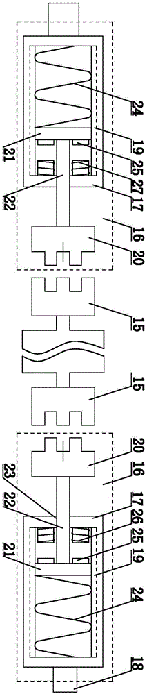
[0028] Embodiment 3: on the basis of the structure described in embodiment 2, as image 3As shown, the clutch includes an A part 15 and a B part 16, the A part 15 is connected with the power output end of the double output gearbox 13, the B part 16 includes a casing 17 and a connecting shaft 18, the connecting shaft 18 is connected to the end surface of the casing 17, and the casing 17 There are slide rails 19 inside, the B part 16 is provided with a mating head 20, the end of the mating head 20 is provided with a bottom plate 21, the mating head 20 and the bottom plate 21 are connected by a pillar 22, the pillar 22 passes through the opening 23 of the shell 17, and the two ends of the bottom plate 21 Located in the slide rail 19, a spring 24 is provided between the bottom plate 21 and the inner bottom surface of the housing 17, an armature 25 is provided on the top surface of the bottom plate 21, and an electromagnet A26 and an electromagnet B27 are respectively provided on th...


PUM


Abstract

The invention provides a quick relay protection test vehicle, and belongs to the field of relay protection tester carry tools. The quick relay protection test vehicle comprises a vehicle body and a device cover. The four corners at the bottom of the vehicle body are each provided with a universal wheel, and one side surface of the vehicle body is provided with a pull bar. The quick relay protection test vehicle is characterized in that a tester grid, a current test wire cylinder, a voltage test wire cylinder and a power supply are disposed inside the vehicle body, rolling and unrolling wire rollers are disposed in the current test wire cylinder and the voltage test wire cylinder, a drive device is disposed between the current test wire cylinder and the voltage test wire cylinder, the rolling and unrolling wire rollers are connected to a power output shaft of the drive device, a control panel is arranged on one side of the vehicle body, and the drive device is connected to the power supply through the control panel. Wires can be arranged in a convenient and neat manner, and the wire arranging efficiency is high.

Description

technical field [0001] The invention provides a relay protection rapid test vehicle, which belongs to the field of relay protection tester carriers. Background technique [0002] The traditional relay protection device testing process is: [0003] 1 Put the box containing the relay protection tester at the relay protection device [0004] 2 Lift the relay protection device out of the box [0005] 3 Take out the voltage test line and current test line from the wire bag, connect one end to the corresponding terminal of the protection device, and the other end to the tester [0006] 4 Start the tester, set the parameters, and start the test [0007] 5 After the test, turn off the power of the tester, organize the voltage test line and current test line, and put them in the line bag. [0008] The method is cumbersome to take up and pay off the wires, the lines are arranged irregularly, and the take-up and take-off efficiency is low. Contents of the invention [0009] The ...

Claims


Application Information

Patent Timeline
Patent Type & Authority Applications(China)
IPC IPC(8): G01R31/327
Inventor 李浩田王瑶瑶高鹏王洪信孙立新侯念国吕云王亚飞周春丽王磊磊郭金霞罗荣钧赵彦龙孙华孙红霞张健农张大海孙涛李玉华王荣伟王同利徐克强
Owner STATE GRID CORP OF CHINA
Why Eureka
Try Eureka