A Servo Loop Decoupling Method for a Four-Axis Inertially Stabilized Platform System

A technology for stabilizing the platform and servo loop, applied in the field of inertial measurement, can solve the problem of incomplete controllability of the servo loop, and achieve the effects of avoiding the gain tending to infinity, accurate decoupling method, and wide applicability

Active Publication Date: 2017-12-22
BEIJING INST OF AEROSPACE CONTROL DEVICES
View PDF2 Cites 3 Cited by
  • Summary
  • Abstract
  • Description
  • Claims
  • Application Information

AI Technical Summary

Problems solved by technology

[0020] It can be seen that at the three gyroscope angular rates When the information is known, there are 4 control execution links The servo loop is not fully controllable

Method used


Image

  • A Servo Loop Decoupling Method for a Four-Axis Inertially Stabilized Platform System
  • A Servo Loop Decoupling Method for a Four-Axis Inertially Stabilized Platform System
  • A Servo Loop Decoupling Method for a Four-Axis Inertially Stabilized Platform System

Examples


Embodiment 1

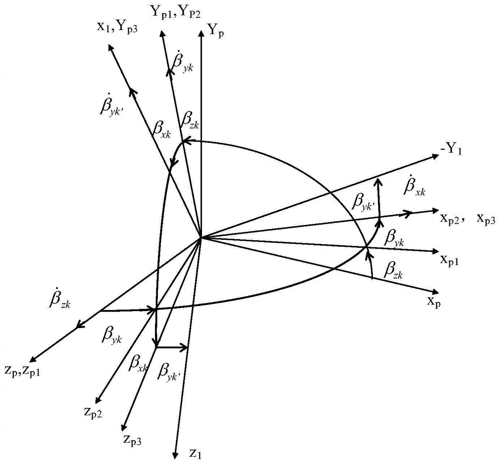
[0067] In this embodiment, the decoupling calculation is performed using the calculation formula of the present invention, wherein the setting conditions are as follows: X p2 Angle of shaft rotation β xk =0; the outer frame revolves around the coordinate system Y of the inner frame p1 Angle of shaft rotation β yk =0; the inner frame revolves around the body coordinate system Z p Angle of shaft rotation β zk =0; that is, the three rotation axes are perpendicular to each other.

[0068] Calculation formula is provided according to the present invention:

[0069]

[0070]

[0071]

[0072]

[0073] From the above calculation results, it can be seen that the input of the three-axis controller of the table body is consistent with the measured values ​​of the respective gyroscopes, and the control input of the following frame is related to the angular velocity of the inner frame.

Embodiment 2

[0075] In this embodiment, the decoupling calculation is performed using the calculation formula of the present invention, wherein the setting conditions are as follows: X p2 Angle of shaft rotation β xk =90°; the outer frame revolves around the coordinate system Y of the inner frame p1 Angle of shaft rotation β yk =0; the inner frame revolves around the body coordinate system Z p Angle of shaft rotation β zk =0.

[0076] Calculation formula is provided according to the present invention:

[0077]

[0078]

[0079]

[0080]

[0081] From the above calculation results, it can be seen that the input of the three-axis controller of the platform is consistent with the measured values ​​of the respective gyroscopes, and the control input of the follower frame is related to the angular velocity of the platform.

Embodiment 3

[0083] In this embodiment, the decoupling calculation is performed using the calculation formula of the present invention, wherein the setting conditions are as follows: X p2 Angle of shaft rotation β xk =90°; the outer frame revolves around the coordinate system Y of the inner frame p1 Angle of shaft rotation β yk =90°; the inner frame revolves around the body coordinate system Z pAngle of shaft rotation β zk =0.

[0084] Calculation formula is provided according to the present invention:

[0085]

[0086]

[0087]

[0088]

[0089] From the above calculation results, it can be seen that, except that the Y and Z axis control quantities of the table body are consistent with the measured values ​​of their respective gyroscopes, the input amount of the servo frame controller is related to the X gyroscope, and the input amount of the outer frame is related to the axis angle of the table body. related to speed.

[0090] The above three embodiments can verify that...


PUM


Abstract

A provided servo loop decoupling method of a four-axle inertial stabilization platform system comprises the following steps: 1, obtaining the angular velocity components at Xp axis, Yp axis and Zp axis according to the angular velocity of a gyroscope installed on a platform body; 2, measuring and obtaining the internal relative rotation angle and angular velocity of the four-axle inertial stabilization platform system; and 3, calculating the synthetic rotation angular velocity of the platform body, an internal frame, an outer frame and a servo frame. The method is capable realizing servo loop decoupling calculation without singular value under the circumstance that the platform system relative rotation angle is an optional value, thereby improving the full attitude adaptation capability of a carrier under the condition of no trajectory constraint.

Description

technical field [0001] The invention relates to the technical field of inertial measurement, in particular to a servo loop decoupling method of a four-axis inertial stable platform system, which is mainly used for full-attitude high-precision navigation in the fields of aviation and aerospace. Background technique [0002] Due to the phenomenon of "frame locking" in the three-axis inertial platform system, it is difficult to meet the requirements of large maneuvering motion of the carrier. Therefore, a four-axis inertial stable platform system is produced. Compared with the three-axis inertial platform system, the four-axis inertial stable platform system adds a follower frame on the basis of the platform body, inner frame and outer frame, and the follower frame is located between the platform outer frame and the base. [0003] The traditional solution is as follows: the follow-up loop signal comes from the corner of the inner frame, and a secant resolver is used for gain co...

Claims


Application Information

Patent Timeline
Patent Type & Authority Patents(China)
IPC IPC(8): G01C21/18G01C21/20
CPCG01C21/18G01C21/20
Inventor 魏宗康
Owner BEIJING INST OF AEROSPACE CONTROL DEVICES
Why Eureka
Try Eureka