Blocking finger device of bending machine

一种折弯机、驱动装置的技术,应用在折弯机领域,能够解决定位精度低、不利精确微调、成本翻等问题,达到保证加工质量、保证定位精度、提高定位精度的效果

Inactive Publication Date: 2016-01-13
ZHUJI MILAN MASCH CO LTD
View PDF7 Cites 3 Cited by
  • Summary
  • Abstract
  • Description
  • Claims
  • Application Information

AI Technical Summary

Problems solved by technology

The manual Z-axis mechanism is currently the most widely used, but it needs to manually enter the working area of ​​the back gauge mechanism to manually adjust the position, which has the risk of work-related injuries, and the positioning accuracy is low
Although the servo Z-axis mechanism reduces the risk of industrial accidents for workers and improves positioning accuracy and digital control, the cost has increased several times, and most customers do not approve of such a cost.
[0005] Moreover, the back of the finger does not have a fine-tuning function, and the front surface is generally designed to be in one-plane contact, which is not conducive to the adjustment of the finger and the zero point of the machine tool during the debugging process, and it is even more unfavorable to realize the precise fine-tuning function

Method used


Image

  • Blocking finger device of bending machine
  • Blocking finger device of bending machine
  • Blocking finger device of bending machine

Examples


Embodiment Construction

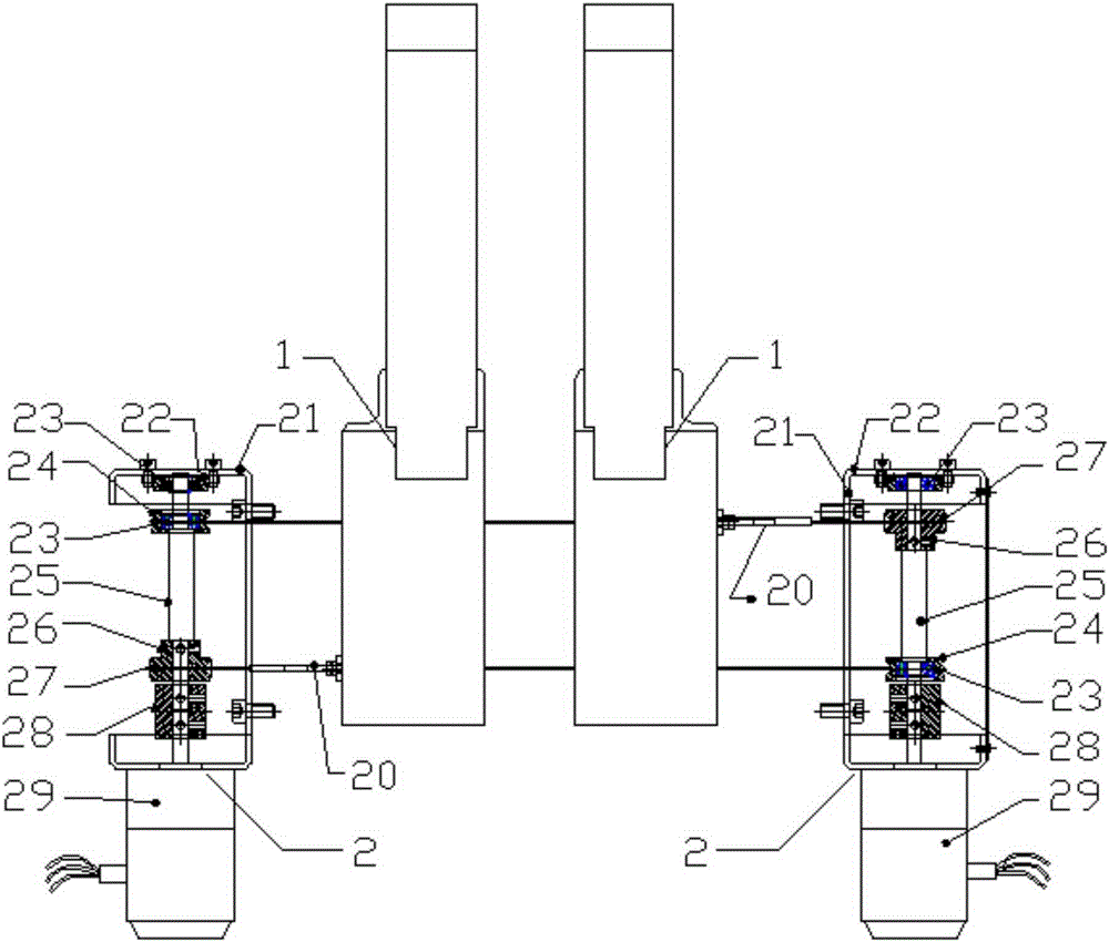
[0022] Such as figure 1 As shown, an automatic finger locking mechanism for a bending machine includes finger driving devices 2 arranged on the left and right sides of the bending machine. Finger 1, the finger 1 is slidably arranged on the Z-axis slide rail of the bending machine, and is driven by the finger drive device 2 to move left and right along the Z-axis slide rail.

[0023] Such as figure 1 As shown, specifically, the finger driving device 2 includes a driving base 21, the driving base 21 has an approximate U-shaped structure, and the driving shaft 25 is vertically and rotatably installed on the driving base 21, and the driving shaft 25 is driven by Driven by a motor 29, the driving shaft is axially equipped with a driving wheel 26 and a driven wheel 24, the driving wheel and the driving shaft are fixed, a bearing 23 is arranged between the driven wheel and the driving shaft, and the driving shafts on the left and right sides The upper driving wheel and the driven w...


PUM


Abstract

The invention discloses a blocking finger device of a bending machine. The blocking finger device of the bending machine comprises blocking finger driving devices arranged on the left side and the right side of the bending machine. A pair of blocking fingers are arranged between the blocking finger driving devices on the left side and the right side side by side. The blocking finger driving devices on the left side and the right side drive the two blocking fingers to move between the left side and the right side. Each blocking finger comprises a blocking finger slider arranged on a Z axis slide rail of the bending machine in a sliding manner. The blocking finger sliders are provided with sliding grooves in the front and back direction. A blocking finger base is arranged in each sliding groove in a sliding manner. The blocking finger sliders are provided with blocking finger front and back micro adjustment devices so that the front and back positions of the blocking finger bases in the sliding grooves can be adjusted. The front ends of the blocking finger bases are connected with a front blocking finger through floating pin shafts. The blocking finger sliders are provided with horizontal adjusting device so that the horizontal position of the front blocking finger can be adjusted. According to the blocking finger device of the bending machine, the blocking fingers have the overall accurate micro adjustment function, and therefore the risk of industrial injuries is avoided to the maximum extent, meanwhile, cost is controlled, and positioning precision is guaranteed.

Description

[0001] The patent application of the present invention is a divisional application of the invention and creation title "An Automatic Finger Locking Mechanism for Bending Machine". The original application date is May 12, 2014, and the application number is 2014101981616. technical field [0002] The invention relates to a bending machine, in particular to a finger stop mechanism of a bending machine. Background technique [0003] In the development of bending machine technology, as the requirements for production efficiency continue to increase, there are more requirements for fast and stable positioning through the fingers. [0004] Among the back gauge mechanisms of bending machines currently on the market, there are the following Z-axis mechanisms for the fingers, one is a manual Z-axis mechanism, and the other is a servo Z-axis mechanism. The manual Z-axis mechanism is currently the most widely used, but it needs to manually enter the working area of ​​the back gauge mec...

Claims


Application Information

Patent Timeline
Patent Type & Authority Applications(China)
IPC IPC(8): B21D43/00
Inventor 王武勇
Owner ZHUJI MILAN MASCH CO LTD
Why Eureka
Try Eureka