
Traction device and logistics transfer car

The technology of a traction device and a locking mechanism is applied in the directions of traction connectors, vehicle parts, transportation and packaging, etc., and can solve the problems of easy damage of the towing mechanism and the locking mechanism, easy to cause safety accidents, high labor intensity of workers, etc. Achieve the effect of avoiding collision and injury, reducing the proportion of work-related injuries, and reducing labor intensity

Pending Publication Date: 2019-11-05
郭子聪
View PDF0 Cites 0 Cited by
  • Summary
  • Abstract
  • Description
  • Claims
  • Application Information

AI Technical Summary

Problems solved by technology

[0005] The purpose of the present invention is to overcome the deficiencies of the prior art, and provide a traction device and a logistics turnover vehicle to solve the problem that workers need to manually operate when connecting and unlocking the towing mechanism and the locking mechanism of the traction device in the prior art. Complicated, the labor intensity of workers is high, it is easy to cause safety accidents, the towing mechanism and the locking mechanism are easily damaged, and the maintenance cost is high. The invention has semi-automatic control of the connection and unlocking of the towing mechanism and the locking mechanism, simple operation, and improved efficiency Reduce the labor intensity of workers, high safety factor, not easy to damage, reduce maintenance costs, etc.

Method used


Image

  • Traction device and logistics transfer car
  • Traction device and logistics transfer car
  • Traction device and logistics transfer car

Examples


Embodiment 1

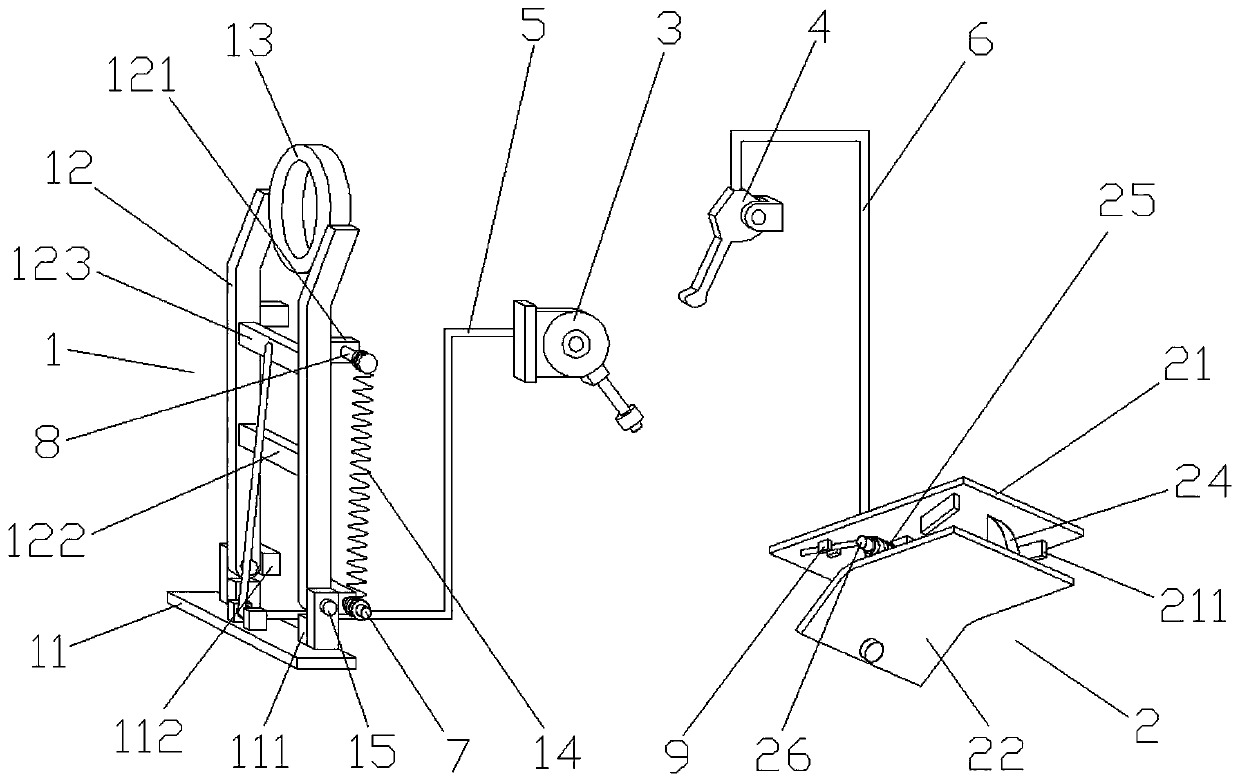
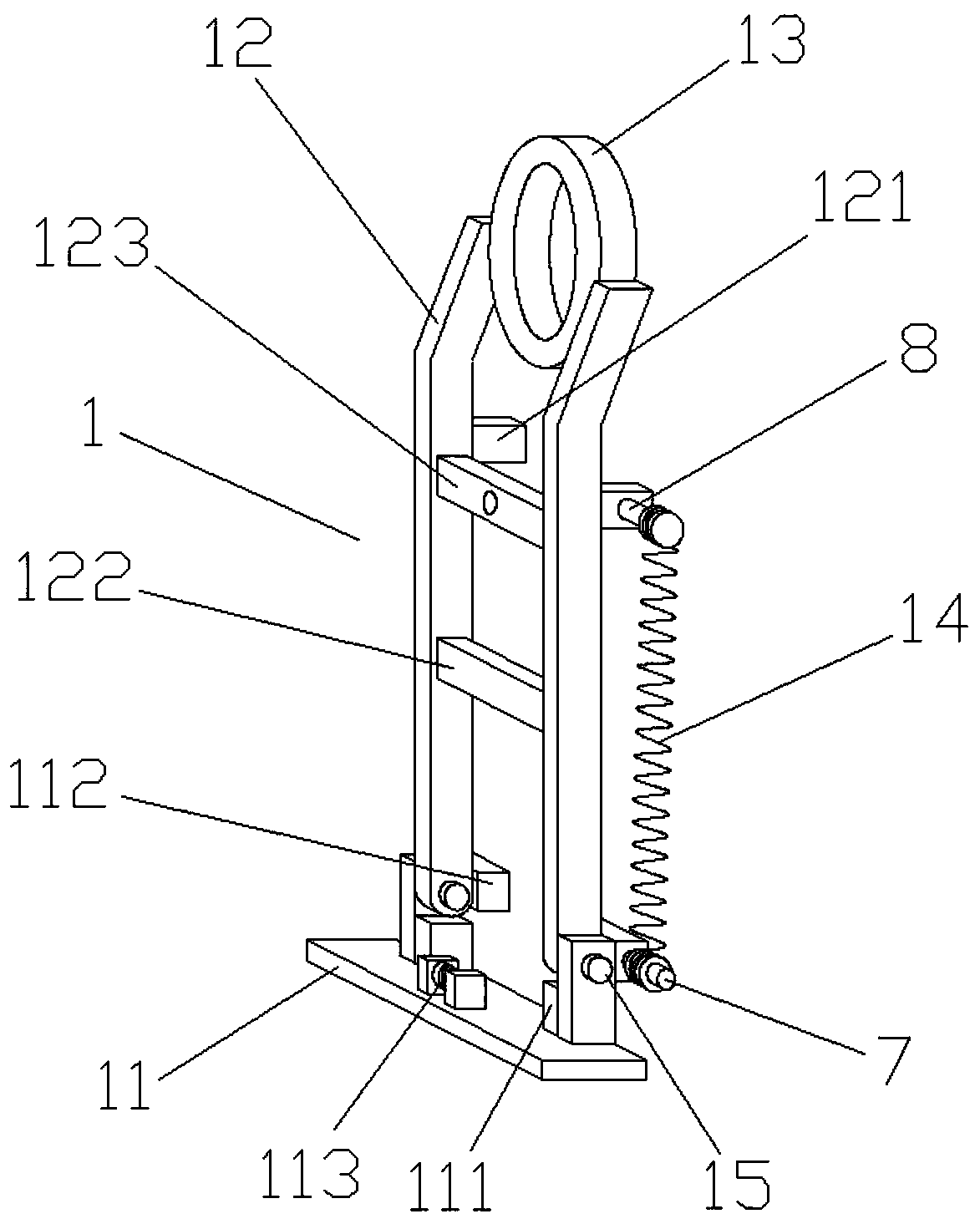
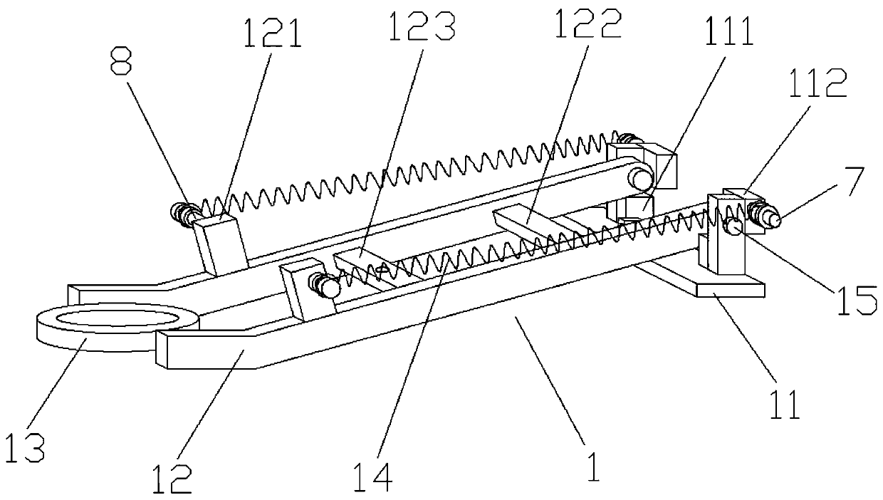
[0024] Embodiment 1 discloses a kind of traction device, such as figure 1 As shown, it includes a trailer mechanism 1, a locking mechanism 2 buckled with the trailer mechanism 1, a hand throttle wrench 3 and a brake handle 4. The hand throttle wrench 3 is connected to the trailer mechanism 1 through a first flexible shaft 5, and the brake The 4 is connected with the locking mechanism 2 through the second flexible shaft 6; as figure 2 and image 3As shown, the towing mechanism 1 includes a fixed seat 11, two tow bars 12, a hanging ring 13 and a tension spring 14, and the bottom ends of the two tow bars 12 are respectively hinged with the front and rear ends of the fixed seat 11 through the first hinge shaft 15. , the hanging ring 13 is fixedly installed between the tops of the two tow bars 12, specifically, the two sides of the hanging ring 13 are respectively welded and fixed to the inner side walls of the tops of the two tow bars 12, the tow bar 12 is in a broken line shape...


PUM


Abstract

The invention discloses a traction device and a logistics transfer car. The traction device comprises a towing-hanging mechanism, a locking mechanism, a hand throttle wrench and a brake handle, wherein the hand throttle wrench is in transmission connection with the towing-hanging mechanism through a first flexible shaft; the brake handle is in transmission connection with the locking mechanism through a second flexible shaft; the towing-hanging mechanism comprises a fixing base, two towing rods, a hanging ring and tension springs; the bottom ends of the towing rods are correspondingly hinged with the front and rear ends of the fixing seat through first hinging shafts; the hanging ring is fixedly mounted between the tops of the towing rods; the tension springs are arranged on the front andrear sides of the fixing seat; the bottom end of the tension spring is higher than the first hinging shafts; and the locking mechanism comprises a fixing plate, a moving plate, clamping seats, a hanging hook and torsion springs. The traction device disclosed by the invention is improved aiming at the problems that a conventional traction device needs to be manually connected and unlocked, both thetime and the effort are wasted, the safety factor is low, and the conventional traction device is easy to damage; and the advantages that the traction device is semi-automatically connected and unlocked, the labor intensity of workers is reduced, the damage possibility is low, and the safety factor is high can be achieved.

Description

technical field [0001] The invention relates to the technical field of traction connectors, in particular to a traction device and a logistics turnover vehicle. Background technique [0002] The traction device includes a towing mechanism and a locking mechanism. The two devices are connected by the buckling of the towing mechanism and the locking mechanism. The towing device is widely used in the field of object transportation. In major production workshops, materials, parts and Products need to be transported by logistics turnover vehicles. In order to improve the efficiency of transportation, logistics turnover vehicles are generally equipped with traction devices, and the logistics turnover vehicles are connected one by one through the traction device, which increases the transportation volume at one time and significantly improves transportation efficiency. . [0003] The towing mechanism and the locking mechanism of the existing traction device need to be manually ope...

Claims


Application Information

Patent Timeline
IPC IPC(8): B60D1/00B60D1/24
CPCB60D1/00B60D1/24B60D2001/005
Inventor 郭子聪其他发明人请求不公开姓名
Owner 郭子聪
Learn More