Vehicle single pedal intelligent speed control method

A speed control and pedal technology, which is applied in the field of single-pedal intelligent speed control of automobiles, can solve the problems of easy errors in sudden braking, complicated driving procedures, and easy misuse, etc., to achieve intelligent control process, meet driving simplification, reduce The effect of error rate

Active Publication Date: 2016-01-13
无锡卡瑞森机械科技有限公司
View PDF10 Cites 8 Cited by
  • Summary
  • Abstract
  • Description
  • Claims
  • Application Information

AI Technical Summary

Problems solved by technology

[0002] The brake device and the clutch of the traditional manual transmission car are designed separately. The driver needs to control the clutch pedal, brake pedal and accelerator pedal. During driving, the driver steps on the brake pedal and the accelerator pedal with his right foot. The accelerator may be mistaken for the brake, causing accidents, and the brake pedal may be used as the clutch pedal, braking without separation of the engine and the chassis of the car, causing damage to the car
[0003] Although the car is now developing from manual to automatic, the clutch pedal is removed, and the gear position is simplified, the driver still needs to control the brake pedal and the accelerator pedal with his right foot. When accelerating or braking, he needs to switch back and forth between the brake pedal and the accelerator pedal. foot, the operation is highly complicated, and it is easy to cause misoperation. If you are not careful, you will mistakenly step on the accelerator as a brake. Especially in an emergency, it is more likely to make mistakes and cause accidents.
[0004] The car intelligent speed control system in the current technology also adopts the mode of one-button start and constant speed cruise, but the commonly used technical driving procedures are more complicated and cannot meet the needs of drivers, especially middle-aged and elderly drivers, who need simplified driving

Method used


Image

  • Vehicle single pedal intelligent speed control method
  • Vehicle single pedal intelligent speed control method
  • Vehicle single pedal intelligent speed control method

Examples


Embodiment 1

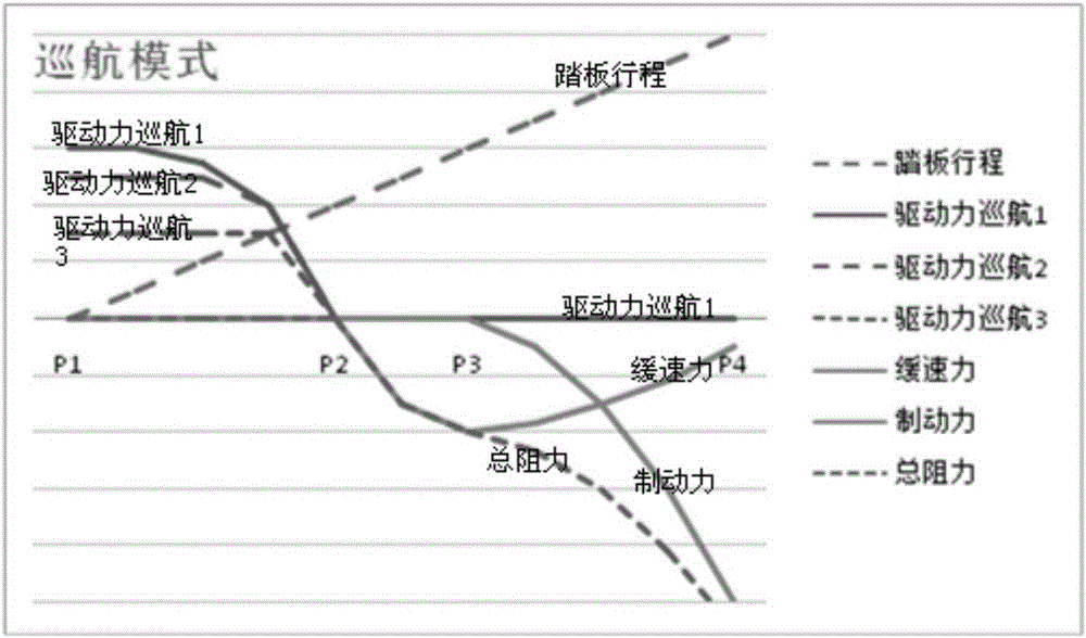
[0053] Such as Figure 1-2 As shown, the automobile intelligent speed control stroke is disclosed in this embodiment, and the above-mentioned automobile intelligent speed control stroke is based on Image 6 In the automotive electronic accelerator and brake integrated device, the above-mentioned automotive electronic accelerator and brake integrated device is provided with a single pedal 11, which combines the traditional brake pedal and accelerator pedal into one, and the design of the pedal can now have the function of speed control. 11. Intelligently control the driving force, retarding force and braking force according to the position of the single pedal 11 stroke, so as to achieve acceleration and deceleration to achieve vehicle speed control; and use electronic and software technology to preset the speed change curve, according to the release Or depress the speed of the above-mentioned pedal 11 to select the speed change curve intelligently.

[0054] The stroke of the p...

Embodiment 2

[0081] For the automobile intelligent speed control method and system disclosed in Embodiment 1, the specific operations and functions are as follows:

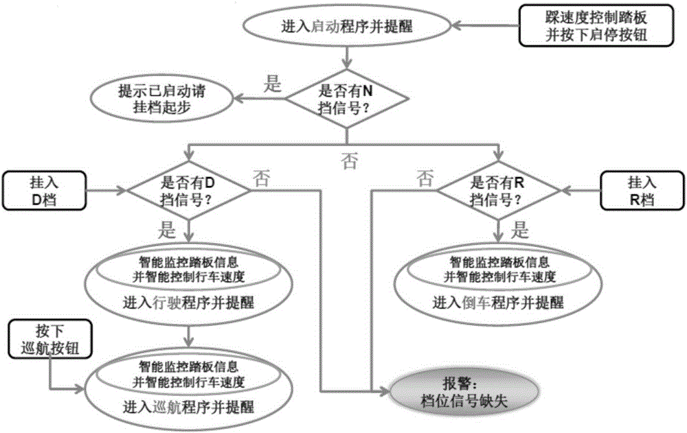
[0082] 1. Start operation: When the driver is driving, only when the speed control pedal is pressed to the P3-P4 braking position and the start-stop button is pressed, the vehicle's drive module (driver or drive unit) can be powered on and enter the ready-to-drive state , release the speed control pedal, and the vehicle starts.

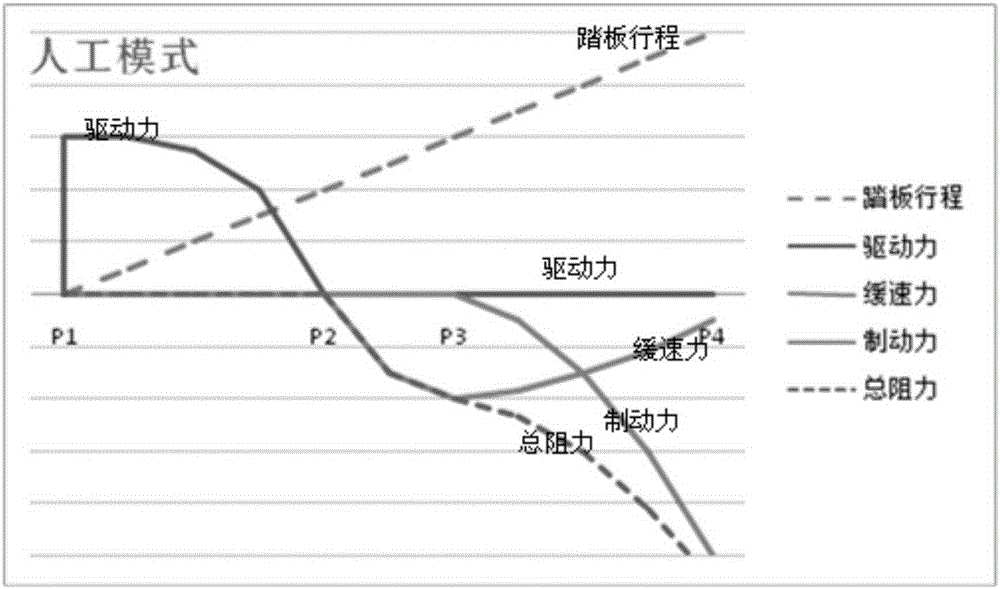
[0083] 2. Manual speed control operation:

[0084] When the driver controls the speed control pedal, the sensor monitors the position of the speed control pedal, so that specific speed, retarding force and braking force can be controlled accordingly.

[0085] When the driver releases or presses down the speed control pedal, the sensor signal is analyzed by the MCU microprocessor software, and the speed at which the driver releases the speed control pedal is calculated, and the corresponding speed cha...

Embodiment 3

[0092] Embodiment 3 discloses a kind of automotive electronic throttle brake integrated device involved in Embodiment 1 and Embodiment 2, such as Image 6 As shown in , it includes a common assembly 1 and a brake assembly 2, wherein the above-mentioned common assembly includes: a pedal 11, a pedal arm 12, a pedal bracket 13, a sensor assembly 14 and a return assembly, and the above-mentioned pedal 11 is arranged on the top of the above-mentioned pedal arm 12 One free end, the other end of the above-mentioned pedal arm 12 is connected to the above-mentioned pedal bracket 13 through the above-mentioned return assembly, the above-mentioned pedal arm 12 rotates around the above-mentioned pedal bracket 13 through the above-mentioned return assembly, and the above-mentioned pedal arm 12 passes through the above-mentioned return assembly return.

[0093] The above-mentioned brake assembly 2 includes: a joint fork 21, a connecting rod one 22 fixed together with the above-mentioned joi...


PUM


Abstract

The invention relates to vehicle intelligent speed control travelling, and relates to correlation of driving force and total resistance with stroke of a pedal in a travelling process of a vehicle. The method comprises: in the stroke from a P1 point to a P2 point, the driving force reducing with the stroke of the pedal increasing, the driving force being maximum between the P1 point and the P2 point and close to the P1 point; in the stroke from the P2 point to a P3 point, the pedal being between the P2 point to and P3 point, and when the pedal is close to the P2 point, starting a retarding mode, a retarding force increasing with increasing of the stroke of the pedal, and the driving force being zero; in a stroke from the P3 point to a P4 point, when the pedal is between the P3 point and the P4 point and is close to the P3 point, starting a braking mode, in the stroke from the P3 point to a P4 point, the total resistance increasing with increasing of stroke of the pedal, and the total resistance being maximum on position close to the P4 point, and the driving force being zero. The control method does not need an accelerator pedal, so driving is simpler, and an existing vehicle control program is changed, directions of accelerating operation and braking operation are opposite and are more aligned with logic. The method prevents regarding the accelerator pedal as the braking pedal, so as to improve traffic safety.

Description

technical field [0001] The invention belongs to the field of automobile control, and in particular relates to an intelligent speed control method for a single pedal of an automobile. Background technique [0002] The brake device and clutch of the traditional manual transmission car are designed separately. The driver needs to control the clutch pedal, brake pedal and accelerator pedal. During driving, the driver steps on the brake pedal and accelerator pedal with his right foot. The accelerator may be mistaken for the brake, causing accidents, and the brake pedal may be used as the clutch pedal, braking without separation of the engine and the chassis of the car, causing damage to the car. [0003] Although the car has now developed from manual to automatic, the clutch pedal has been removed, and the gear position has been simplified, the driver still needs to control the brake pedal and the accelerator pedal with his right foot. When accelerating or braking, he needs to sw...

Claims


Application Information

Patent Timeline
Patent Type & Authority Applications(China)
IPC IPC(8): B60W30/14
CPCB60W30/143
Inventor 刘中岳贺中义刘韬
Owner 无锡卡瑞森机械科技有限公司
Why Eureka
Try Eureka