Electronic boundary apparatus, unmanned flight system, unmanned aerial vehicle monitoring method

A technology of unmanned aerial vehicle and boundary system, which is applied in the field of monitoring of the flying area of ​​unmanned aerial vehicle, can solve the problems of inability to complete, the ground control system is disconnected, the signal is weakened, etc., and achieves the effect of avoiding disconnection

Active Publication Date: 2016-01-13
杨珊珊
View PDF14 Cites 28 Cited by
  • Summary
  • Abstract
  • Description
  • Claims
  • Application Information

AI Technical Summary

Problems solved by technology

However, in the above technical solution, when the UAV is far away from the ground control system, the signal is too weak, or when the signal transmission between the UAV and the ground control system is interfered, it is easy for the UAV positioning i...

Method used


Image

  • Electronic boundary apparatus, unmanned flight system, unmanned aerial vehicle monitoring method
  • Electronic boundary apparatus, unmanned flight system, unmanned aerial vehicle monitoring method
  • Electronic boundary apparatus, unmanned flight system, unmanned aerial vehicle monitoring method

Examples


Embodiment 1

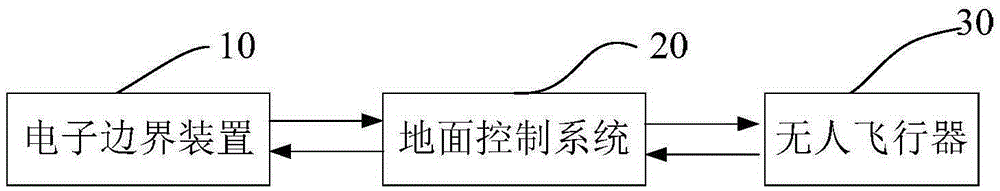
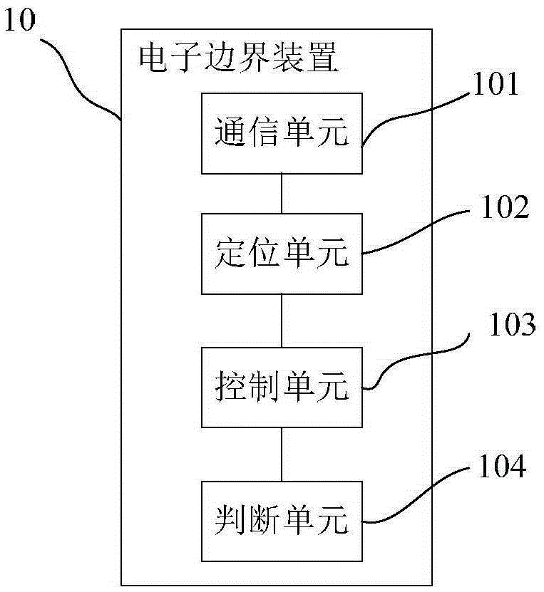
[0042] Figure 1a It is a schematic diagram of the basic composition of the electronic boundary system disclosed in this embodiment. Such as Figure 1a As shown, the electronic boundary system includes an electronic boundary device 10, one or more unmanned aerial vehicles 30, and a ground control system 20, and the above-mentioned electronic boundary device 10 is set independently of the above-mentioned unmanned aerial vehicle 30 or the ground control system 20. In other words, the above-mentioned electronic boundary device 10 can be moved to any position according to specific needs, and the above-mentioned electronic boundary device can be placed at a predetermined position to determine the above-mentioned flight area. In addition, in this embodiment, the flying area of ​​the UAV 30 is determined based on the location information of the electronic border device 10 . Among them, such as Figure 1a As shown, the above-mentioned electronic boundary device 10 , the above-mentione...

Embodiment 2

[0069] The difference between this embodiment and Embodiment 1 is that in this embodiment, the electronic border system includes multiple electronic border devices 10 . That is to say, in this embodiment, a plurality of electronic boundary devices 10 are arranged on the flight route preset by the unmanned aerial vehicle 30. In this way, when the flight area is set with the position of the electronic boundary device 10 as the boundary, how many The area formed around each electronic boundary device 10 constitutes the flight area of ​​the unmanned aerial vehicle 30, that is, the intersection of each flight area set with the position of each electronic boundary device 10 as the boundary constitutes the flight area of ​​the unmanned aerial vehicle 30. Flight area; and when the flight area is set with the position of the electronic boundary device 10 as the center, the union of each flight area set with the position of each electronic boundary device 10 as the center constitutes the...

Embodiment 3

[0077] The difference between this embodiment and Embodiment 1 or Embodiment 2 is that in this embodiment, in order to enable the electronic boundary device to have a specific monitoring range, preferably, the above-mentioned electronic boundary device 10 also includes a pre-stored monitoring range information The storage unit and a verification unit for identifying and verifying the identity information of the unmanned aerial vehicle 30 and judging whether it belongs to the above-mentioned monitoring range information. Specifically, the above monitoring range information may be related information of one or more unmanned aerial vehicles that need to be monitored.

[0078] Figure 5 It is the flight monitoring method of using the electronic boundary device to monitor the flight of the unmanned aerial vehicle in this embodiment. Specifically, such as Figure 5 As shown, at least one electronic boundary device 10 as mentioned above is placed at a preset position, and the fligh...


PUM


Abstract

The invention mainly provides an electronic boundary apparatus for setting a flight region of an unmanned aerial vehicle. The electronic boundary apparatus comprises a communication unit for receiving information and feeding information back and a positioning unit for localizing location of the electronic boundary apparatus. The electronic boundary apparatus is arranged by being independent to the unmanned aerial vehicle; and a flight region of the unmanned aerial vehicle is generated based on the location information of the electronic boundary apparatus. In addition, the invention also provides an electronic boundary system containing the electronic boundary apparatus and a monitoring method of an unmanned aerial vehicle. According to the technical scheme, a flight region boundary can be set rapidly; and a flight path of an unmanned aerial vehicle can be monitored in real time even when signal transmission between the unmanned aerial vehicle and a ground control system can not be carried out normally, so that flight beyond the safety flight range can be avoided and thus a phenomenon of loss of communication of an unmanned aerial vehicle can be prevented.

Description

Technical field: [0001] The invention mainly relates to the field of unmanned aerial vehicles, and in particular to the monitoring aspect of the flight area of ​​the unmanned aerial vehicles. Background technique: [0002] Unmanned aircraft, referred to as unmanned aerial vehicle (UAV), is a new concept of flying equipment in rapid development. Etc. Unmanned aerial vehicles are equipped with multiple types of sensors, which can realize real-time image transmission, detection of high-risk areas, etc., and at present, the scope of use of unmanned aerial vehicles has been expanded to three major fields: military, scientific research, and civilian use, and has a wide range of applications. [0003] However, although the existing unmanned aerial vehicle can achieve long-term and long-distance target detection or target tracking operations, but because its flight area may not have been set in detail, the unmanned aerial vehicle may exist during flight. Security risks. For examp...

Claims


Application Information

Patent Timeline
IPC IPC(8): G08G5/00
Inventor 杨珊珊
Owner 杨珊珊
Why Eureka
Try Eureka