Low-altitude flight gridding management method

A management method and low-altitude flight technology, which is applied in the field of grid-based low-altitude flight management, can solve problems such as easy confusion, unintuitive management interface, and altitude and latitude response to aircraft flight conditions, etc.

Active Publication Date: 2022-06-28
北京大唐永盛科技发展有限公司
View PDF9 Cites 1 Cited by
  • Summary
  • Abstract
  • Description
  • Claims
  • Application Information

AI Technical Summary

Problems solved by technology

[0004] However, the effective management of low-altitude airspace is still an urgent research topic. In the existing low-altitude management systems, most of them use a two-dimensional perspective for route management, which cannot reflect the flight situation of the aircraft from the altitude latitude, so the management interface is not intuitive. When there are many aircraft under management, it is easy to cause confusion

Method used


Image

  • Low-altitude flight gridding management method
  • Low-altitude flight gridding management method
  • Low-altitude flight gridding management method

Examples


Embodiment 1

[0027] A low-altitude flight grid management method is implemented through the following steps;

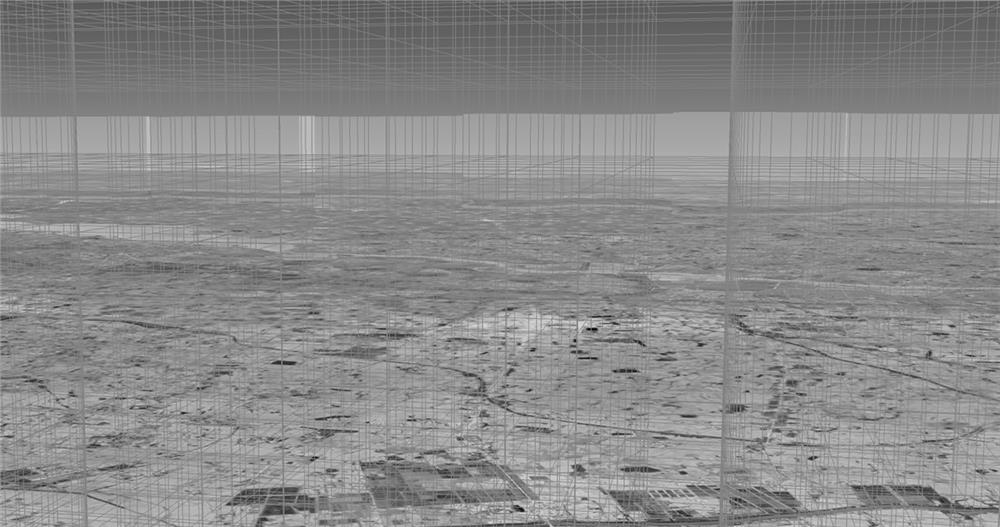
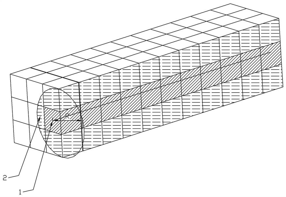
[0028] S1 is based on a three-dimensional geographic information system, and divides the management airspace into several continuous three-dimensional spatial grids; each grid has different grid characteristics; the grid characteristics include grid length, width and height; such as figure 1 shown;

[0029] S2 obtains the longitude, latitude and elevation information of the first UAV's expected flight path 1, and superimposes it with the gridded three-dimensional space;

[0030] S3 marks the grid with the first color 2 that overlaps the expected flight path.

[0031] The length, width and height of the grid can be set according to the type of UAV. The length, width and height of the grid (ie the difference in longitude, latitude, and elevation) can limit the spatial range contained in each grid. , so that after obtaining the longitude, latitude and elevation information of each ...

Embodiment 2

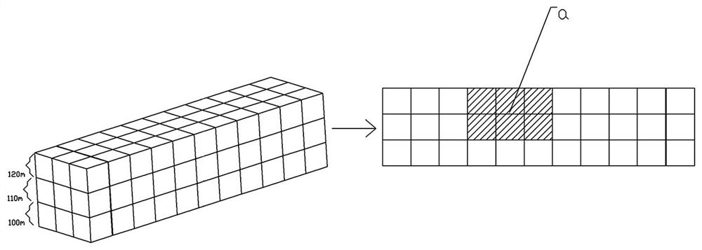
[0049] On the basis of Embodiment 1, further, the three-dimensional space grid is divided into several height layers from bottom to top according to the type of UAV, each height layer has different grid features, and the grid features include grid Length, grid width and grid height.

[0050] Each different altitude layer can correspond to different types of UAVs. The larger the load, speed and volume of the UAV, the higher the flight height should be, and the corresponding grid management space should also be set larger.

[0051] Further, the grid features also include speed limit and UAV type; real-time acquisition of UAV real-time position information, type information and speed information, while taking the speed limit and UAV type as constraints, if there is no one. If the aircraft type information does not match the UAV type attribute of the grid, or the flight speed exceeds the limit speed, the grid will be highlighted with a color mark and an early warning will be issue...

Embodiment 3

[0053] On the basis of Embodiment 1, further, in step S3, after obtaining the expected flight path of the first UAV, first perform a flight rehearsal in the grid space, and the rehearsal steps include:

[0054] S31 obtains UAV type information, flight speed, expected flight period, and expected flight path, and overlaps the expected flight path with the grid space, and counts the grids covered by the flight path;

[0055]S32, according to the number of covered grids and the expected flight period, calculate the time period during which the drone occupies the grid, and mark the grid with a time attribute;

[0056] S33 detects whether there are duplicate grids with other drones' expected flight paths;

[0057] S34 If there are duplicate grids, determine whether the difference between the estimated arrival times of multiple UAVs passing through the same grid is greater than the first threshold; if it is less than or equal to the first threshold, re-planning the path.

[0058] li...


PUM


Abstract

The invention provides a low-altitude flight gridding management method, which is characterized by being realized by the following steps of: (1) performing gridding management; the method comprises the following steps: S1, dividing a management airspace into a plurality of continuous three-dimensional space grids based on a three-dimensional geographic information system; each grid has different grid characteristics; the grid characteristics comprise grid length, width and height; s2, acquiring longitude, latitude and elevation information of a predicted flight path 1 of the first unmanned aerial vehicle, and superposing the longitude, latitude and elevation information with the gridding three-dimensional space; s3, marking the grids overlapped with the predicted flight path with a first color 2; according to the method, airspace gridding division is carried out on the basis of a geographic information system, so that visual management of low-altitude flight is realized, and the management efficiency is improved.

Description

technical field [0001] The invention belongs to the technical field of low-altitude flight management, and in particular relates to a gridded low-altitude flight management method. Background technique [0002] Continue to promote the reform of the air traffic control system, improve the joint operation mechanism of military and civilian air traffic control, implement the refined management of airspace resources classification, optimize the national air route network, and deepen the reform of low-altitude airspace management. [0003] The development of low-altitude airspace resources will be a new direction for my country's transportation development, with broad market prospects. [0004] However, the effective management of low-altitude airspace is still a subject that needs to be studied urgently. Most of the existing low-altitude management systems use a two-dimensional perspective for route management, which cannot reflect the flight situation of the aircraft from the a...

Claims


Application Information

Patent Timeline
Patent Type & Authority Applications(China)
IPC IPC(8): G06F30/20G06Q10/04G06Q50/30
CPCG06F30/20G06Q10/047G06Q50/30Y02T10/40
Inventor 朱谞范文阳章和盛蔡宗智刘海辉蔡桂斌郑金淳郑友华章和佳
Owner 北京大唐永盛科技发展有限公司
Why Eureka
Try Eureka