Permanent magnet speed adjuster with fixed magnetic gap

A permanent magnet governor and fixed magnet technology, applied in the direction of permanent magnet clutches/brakes, etc., can solve the problem of not being able to rotate to drive the load, etc., to save installation space, reduce heat generation, and reduce material consumption.

Active Publication Date: 2016-01-13
刁俊起
View PDF5 Cites 1 Cited by
  • Summary
  • Abstract
  • Description
  • Claims
  • Application Information

AI Technical Summary

Problems solved by technology

In order to solve the above problems, the patent CN201520071349 proposes a permanent magnet governor with a fixed magnetic gap, but when the first inner magnetic rotor and the second inner magnetic rotor rotate, the corresponding relationship between the first permanent magnet and the second permanent magnet The polarity of the magnetic pole is constantly switched between the same and different, which causes the driven shaft to oscillate back and forth in two directions, and cannot normally rotate in one direction to drive the load

Method used


Image

  • Permanent magnet speed adjuster with fixed magnetic gap
  • Permanent magnet speed adjuster with fixed magnetic gap
  • Permanent magnet speed adjuster with fixed magnetic gap

Examples


Embodiment 1

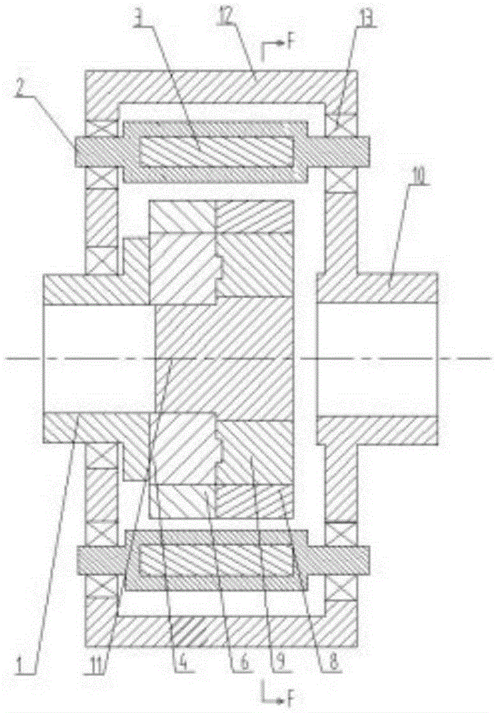
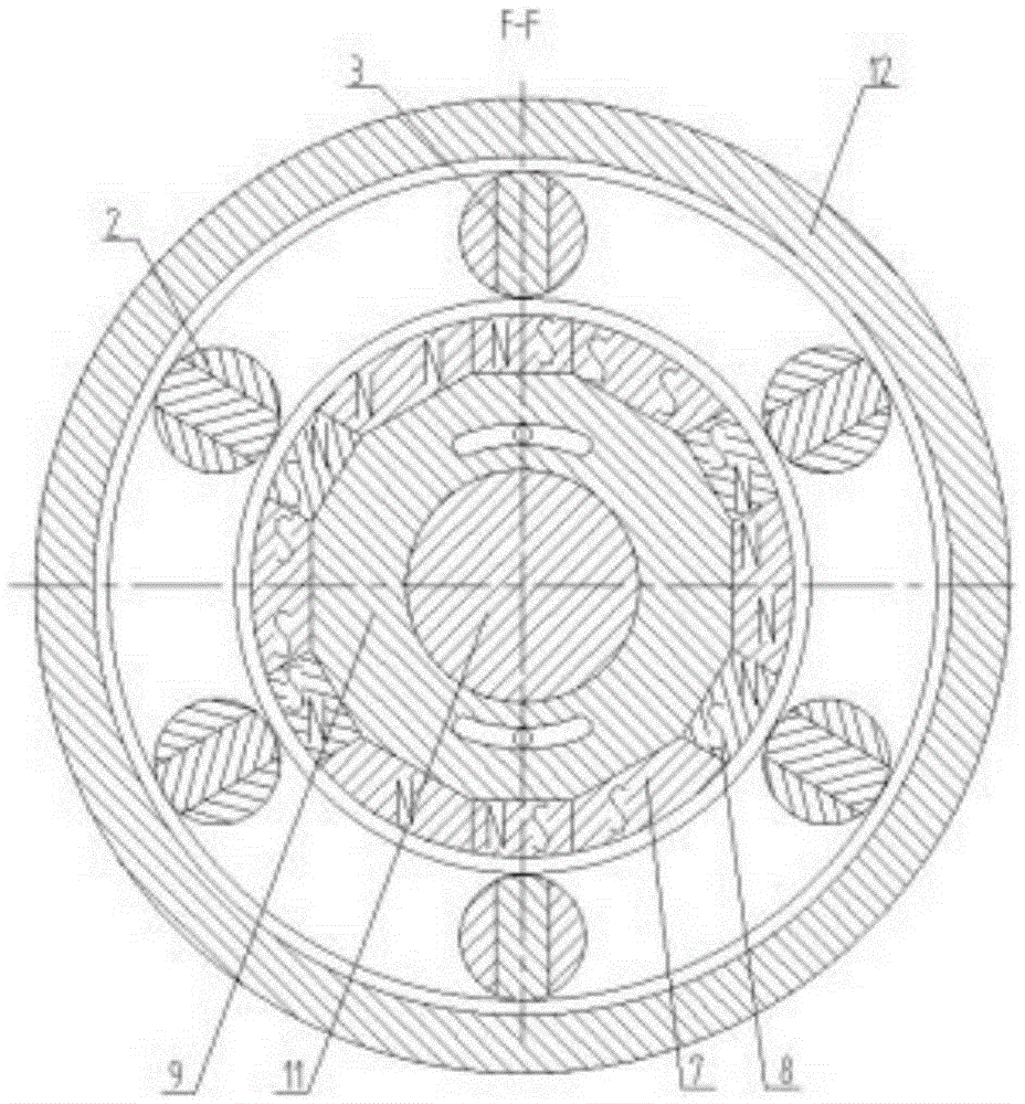
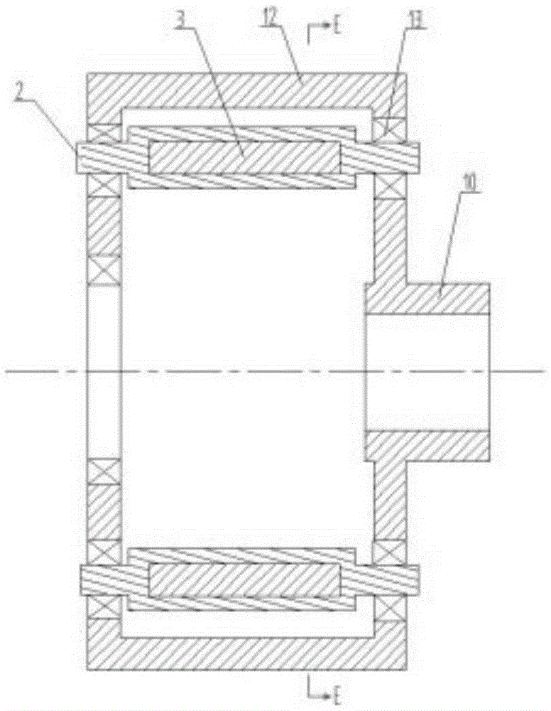
[0025] A permanent magnet governor with a fixed magnetic gap, including a first inner magnetic rotor 4 and a second inner magnetic rotor 9 through which a driving shaft 1 passes concentrically, an outer magnetic rotor frame 12 connected to a driven shaft 10, and an outer magnetic rotor 2. The outer magnetic rotor 2 is mounted on the outer magnetic rotor frame 12 through bearings 13 assembled at both ends, and the bearings 13 can be one-way bearings or two-way bearings. The outer magnetic rotor 2 has at least two outer permanent magnets 3 uniformly distributed along its inner circumferential surface, and the first inner magnetic rotor 4 and the second inner magnetic rotor 9 are both circumferentially distributed along their respective outer circumferential surfaces. At least two first inner permanent magnets 6 and second inner permanent magnets 8 are evenly distributed, and the magnetic poles of each inner permanent magnet are arranged along the circumferential direction, and th...

Embodiment 2

[0027] The invention relates to a permanent magnet governor with a fixed magnetic gap. The magnetic poles of each inner permanent magnet are arranged radially, and the adjacent side magnetic poles of two adjacent inner permanent magnets on the same inner magnetic rotor are magnetically different. All the other parts are the same as the first embodiment.


PUM


Abstract

The invention relates to a permanent magnet speed adjuster with a fixed magnetic gap, which comprises a first inner magnetic rotor, a second inner magnetic rotor and an outer magnetic rotor frame, wherein a driving shaft concentrically passes through the first inner magnetic rotor and the second inner magnetic rotor; the outer magnetic rotor frame is connected with a driven shaft; the outer magnetic rotor frame is provided with an outer magnetic rotor via a bearing; the first inner magnetic rotor and the second inner magnetic rotor are both provided with at least two first inner permanent magnets and second inner permanent magnets distributed circumferentially and uniformly along the outer circumferential surfaces; and the first inner magnetic rotor is provided with a magnetic circuit adjustment executor driving the first inner magnetic rotor to rotate relative to the second inner magnetic rotor. As the fixed magnetic gap structure is adopted, the meshing area of the speed adjuster is greatly improved, the assembly difficulty is reduced, heat generation is reduced, the speed adjustment range is increased, rare earth materials are saved, and the torque transfer capability is greatly improved. As the bearing structure is adopted, the phenomenon that as the driven shaft shocks back and forth along two directions, the driven shaft can not rotate normally along one direction to drive a load can be avoided.

Description

technical field [0001] The invention relates to a permanent magnet governor, in particular to a permanent magnet governor with a fixed magnetic gap. Background technique [0002] The permanent magnet speed governor uses the magnetic coupling speed of the permanent magnet to realize the soft (magnetic) connection between the motor and the load, without any harmonic generation affecting the power grid, and has high reliability. , Inflammable and explosive, voltage instability and lightning and other harsh environments, greatly reducing mechanical vibration, widely used in electric power, steel, metallurgy, petrochemical, papermaking, municipal, ships, irrigation and mining industries. At present, the commonly used permanent magnet governors realize the speed adjustment by adjusting the air gap. The magnetic circuit regulator consumes a lot of power, and has disadvantages such as poor torque transmission capability, high assembly difficulty, and waste of a large amount of rare ...

Claims


Application Information

Patent Timeline
Patent Type & Authority Applications(China)
IPC IPC(8): H02K49/10
Inventor 刁俊起李强张磊王忠亮王秀张学凯
Owner 刁俊起
Why Eureka
Try Eureka