
Electrical power element mounting device provided with radiating fins

A technology of electric power and heat dissipation fins, which is applied in the field of electric power and can solve the problems of difficulty in maintaining power devices, interference in operating power devices, and difficulty in cooling and dissipating heat.

Inactive Publication Date: 2016-01-13
范盛林
View PDF0 Cites 0 Cited by
  • Summary
  • Abstract
  • Description
  • Claims
  • Application Information

AI Technical Summary

Problems solved by technology

However, it is still difficult to play a targeted role in the cooling and heat dissipation of the main heat-generating devices that are significantly higher than other devices during use.
Moreover, some centralized heat dissipation equipment is likely to cause difficulties in the maintenance of such main power devices, which may interfere with the positioning and installation of such power components during operation, and may also cause interference to the operation of such power devices

Method used


Image

  • Electrical power element mounting device provided with radiating fins
  • Electrical power element mounting device provided with radiating fins
  • Electrical power element mounting device provided with radiating fins

Examples


Embodiment Construction

[0011] Combine below Figure 1-3 The present invention will be described in detail.

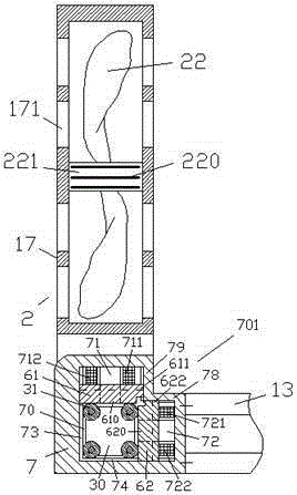
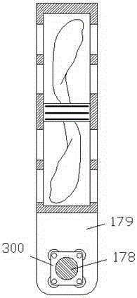
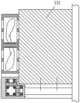
[0012] refer to figure 1 , according to the embodiment of the power and electrical component installation device with cooling fins, including a beam 13 for fixing the power and electrical components 131 and a cooling assembly connected to the end of the beam 13, the cooling assembly includes The housing frame 7 at the end of the beam 13 and the fan device 2 that can rotate relative to the housing frame 7, the fan device 2 includes a mounting housing 17 with an airflow opening 171, installed on The fan motor 221 in the installation housing and the fan blade 22 power-connected with the fan motor 221, the casing surface of the fan motor 221 is provided with a plurality of cooling fins 220 in order to place the fan motor 221 on the The heat generated during operation is absorbed and dissipated, so as to prevent the fan motor 221 from being burned due to excessive temperature during long-term op...


PUM


Abstract

The invention provides an electrical power element mounting device provided with radiating fins. The electrical power element mounting device comprises a cross beam (13) and a cooling assembly, wherein the cross beam (13) is used for fixing an electrical power element (131); the cooling assembly is connected with the end part of the cross beam (13), and the cooling assembly comprises a shell body frame (7) which is fixed to the end part of the cross beam (13) and a fan device (2) which can rotate relative to the shell body frame (7); the fan device (2) comprises a mounting shell body (17) provided with an airflow flowing port (171), a fan motor (221) mounted inside the mounting shell body (17) and fan blades (22) which are in power connection with the fan motor (221); and a plurality of the radiating fins (220) are transversely arranged on the surface of an outer shell of the fan motor (221) for absorbing and radiating heat generated by the fan motor (221) in operation, thereby preventing the fan motor (221) from burning down due to too high temperature in long-time operation.

Description

technical field [0001] The invention relates to the field of electric power, in particular to a power electric component installation device with cooling fins. Background technique [0002] In the field of power and electricity, some electrical components such as relay switches, overload protectors, circuit breakers and other devices often generate heat during use. This heating phenomenon will not directly affect the safety of electricity use and equipment installation in a short period of time, but the long-term heating and overheating phenomenon will have an adverse effect on the mechanical structure of the device's shell, bracket, etc., and cause the mechanical strength of these structures to fail. , resulting in serious accidents. [0003] In cooling devices for these devices, fans uniformly installed on the box body are often used to centrally dissipate heat from the internal space containing these devices. This plays a good role in improving the working environment a...

Claims


Application Information

Patent Timeline
IPC IPC(8): H05K7/20
Inventor 范盛林
Owner 范盛林
Learn More