
Test device for double-pole electric leakage protection switch

A technology of leakage protection switch and test device, applied in the direction of measuring device, circuit breaker test, measurement of electricity, etc., can solve the problems of hidden safety hazards, failure of leakage switch, difficulty in achieving leakage protection, etc., to prevent electricity safety accidents, The effect of eliminating security risks

Active Publication Date: 2016-01-20
SHENZHEN POWER SUPPLY BUREAU
View PDF7 Cites 0 Cited by
  • Summary
  • Abstract
  • Description
  • Claims
  • Application Information

AI Technical Summary

Problems solved by technology

[0003] At present, because the user's electricity voltage generally adopts single-phase 220V, most users use bipolar two-wire leakage protection switches in their homes. The quality is also mixed, so it is difficult for most household leakage protection switches to achieve the purpose of leakage protection and overload prevention; 2. Since most electricity users lack the maintenance awareness of leakage switches, they cannot perform regular test trips, which leads to aging of leakage switches. Sensitivity and other problems occur from time to time; 3. Due to the variety of low-voltage wiring methods in the user's home, there are wrong wirings such as connecting the N wire (zero wire) and the PE wire (ground wire) in parallel, and swapping the L wire (fire wire) and N wire at the socket. situation, make the leakage switch lose its function

Method used


Image

  • Test device for double-pole electric leakage protection switch
  • Test device for double-pole electric leakage protection switch
  • Test device for double-pole electric leakage protection switch

Examples


Embodiment Construction

[0021] In order to make the object, technical solution and advantages of the present invention clearer, the present invention will be further described in detail below in conjunction with the accompanying drawings.

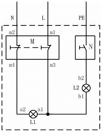
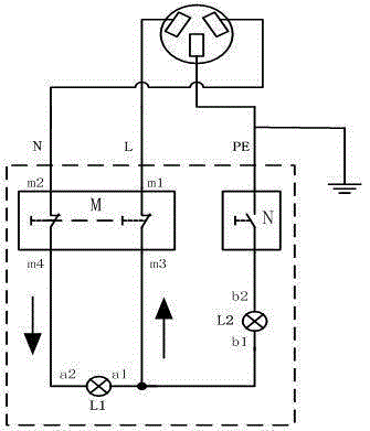
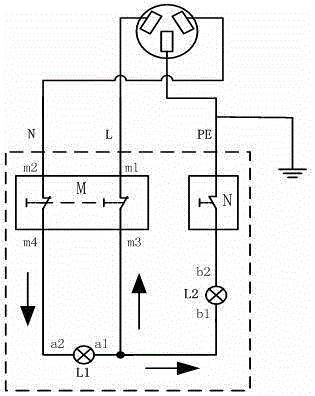
[0022] Such as figure 1 As shown, it is a test device for a bipolar leakage protection switch provided by the embodiment of the present invention, which is matched with the first bipolar leakage protection switch connected to the live line L and the neutral line N in the user's home. The test device includes the first Two bipolar leakage protection switch M, bypass switch N, first display part L1 and second display part L2; wherein,

[0023] The second bipolar leakage protection switch M includes a live line input terminal m1 that can be connected to the first bipolar leakage protection switch through the live line L, and a neutral line input terminal m2 that can be connected to the first bipolar leakage protection switch through the neutral line N, and The live ...


PUM


Abstract

The invention provides a test device for a double-pole electric leakage protection switch which is matched with a first double-pole electric leakage protection switch. The test device comprises a second double-pole electric leakage protection switch, a bypass switch, a first display component and a second display component, wherein the second double-pole electric leakage protection switch comprises a live line input end connected with the first double-pole electric leakage protection switch, a zero line input end connected with the first double-pole electric leakage protection switch, a live line output end connected with a first end of the first display component, and a zero line output end connected with a second end of the first display component; the bypass circuit comprises one end connected with a ground line and the other end connected with a second end of the second display component; and the second display component further comprises a first end which is connected with the live line output end of the second double-pole electric leakage protection switch and the first end of the first display component. According to implementation of the test device provided by the invention, the operation reliability of double-pole electric leakage protection switches of users at home can be effectively tested, the accuracy of a power utilization wiring mode is judged, and the purposes of eliminating potential safety hazards and preventing safety accidents in power utilization are realized.

Description

technical field [0001] The invention relates to the technical field of leakage protection switches, in particular to a test device for bipolar leakage protection switches. Background technique [0002] With the increase of users' household electrical equipment, the user's electricity load has also increased, and safety problems such as electric shocks caused by leakage, burning of electrical appliances, and even fires have become more and more prominent. Household leakage protection switch, as the "first protector" of the user's electricity safety, its performance and quality play an important role in improving the level of safe electricity use, reducing personal electric shock casualties, equipment leakage protection and electrical fire accidents. [0003] At present, because the user's electricity voltage generally adopts single-phase 220V, most users use bipolar two-wire leakage protection switches in their homes. The quality is also mixed, so it is difficult for most ho...

Claims


Application Information

Patent Timeline
Patent Type & Authority Applications(China)
IPC IPC(8): G01R31/327G01R31/02
Inventor 丛少峰姚杰淳韩聪张佳森黄慧山杨静祥曹阳
Owner SHENZHEN POWER SUPPLY BUREAU
Learn More