Smart device control circuit with state hold function
A state maintenance and control circuit technology, applied in the direction of electrical program control, program control in sequence/logic controller, etc., can solve problems such as the risk of power consumption of smart devices
- Summary
- Abstract
- Description
- Claims
- Application Information
AI Technical Summary
Problems solved by technology
Method used
Image

Examples
Embodiment 1
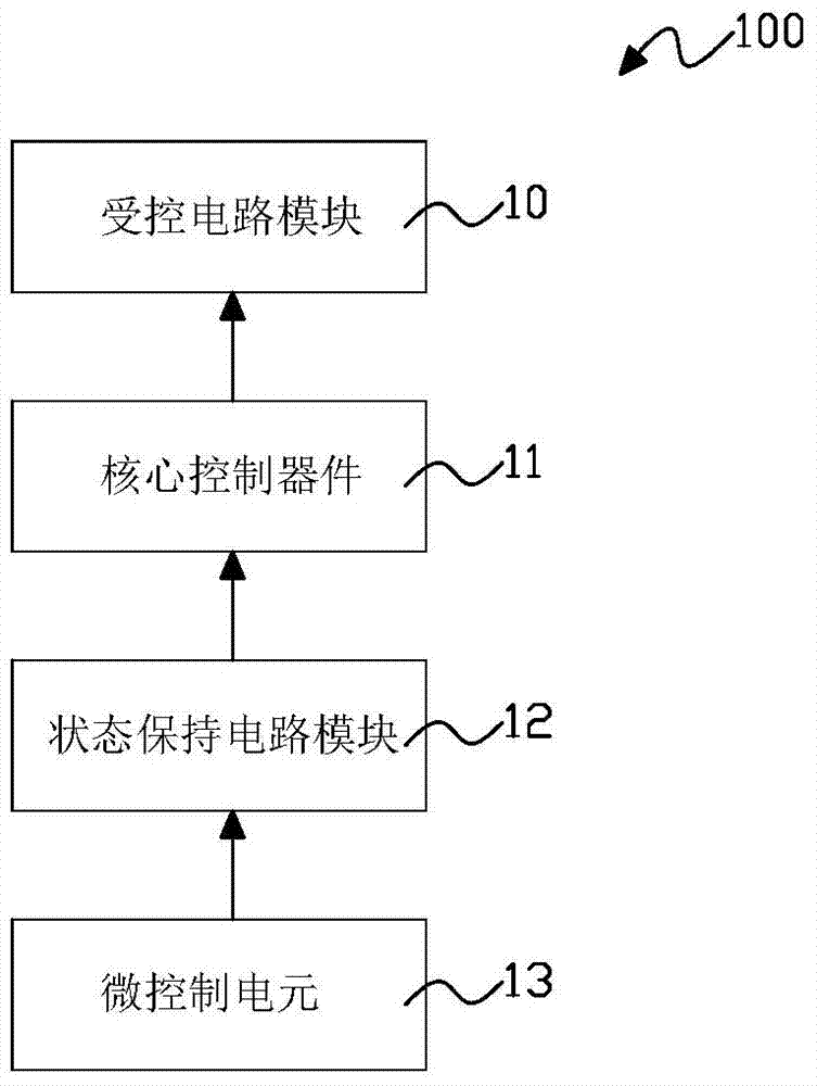
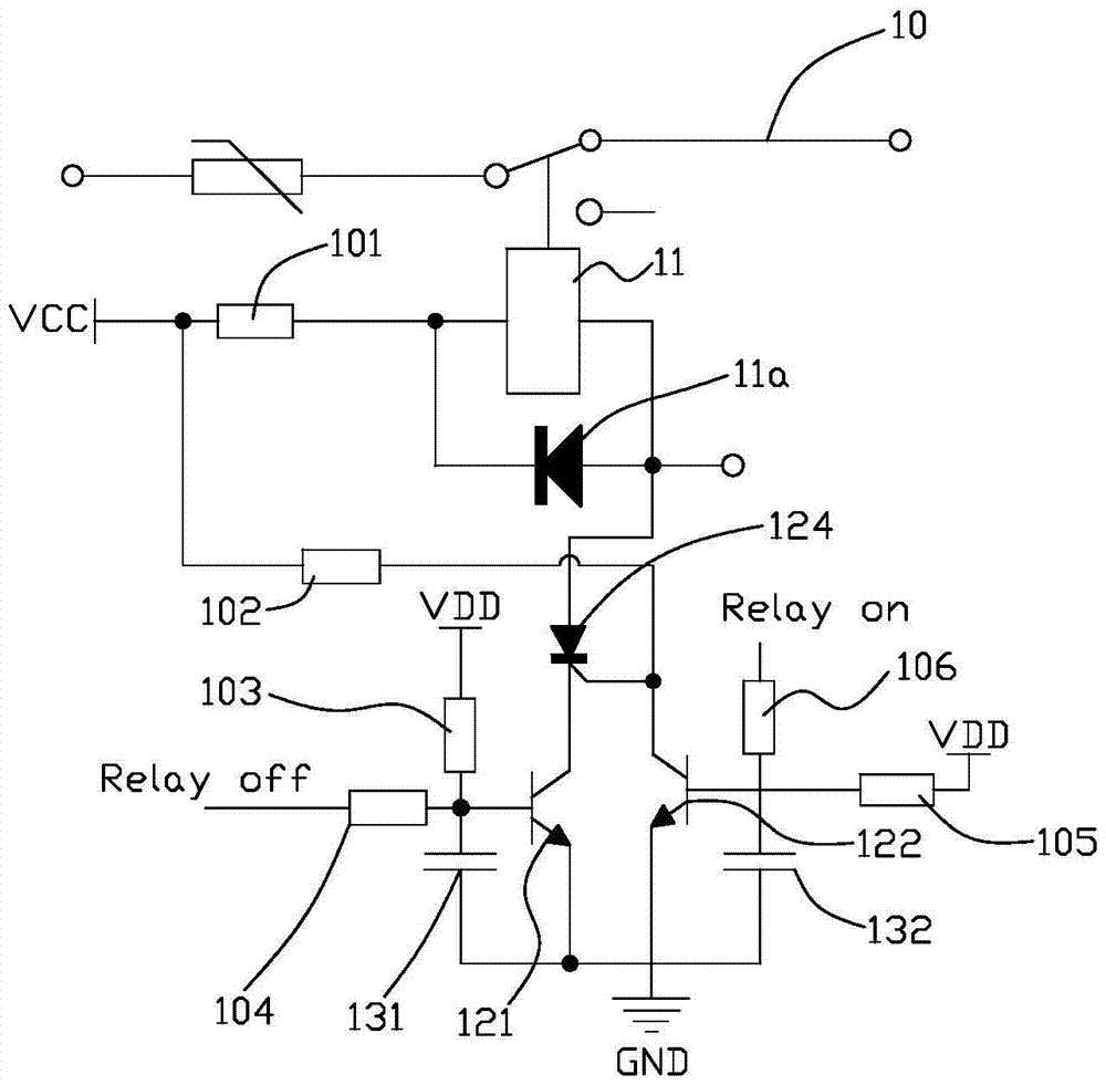
[0049] refer to figure 2 , which is a circuit diagram of a specific embodiment of the above-mentioned smart device control circuit 100 . Such as figure 2 As shown, in this embodiment, the core control device 11 is a DC relay, and the DC relay is connected in reverse parallel with a diode 11a. That is to say, the input end of the relay is electrically connected to the cathode of the diode 11a, and the output end of the relay is electrically connected to the anode of the diode 11a. The function of the diode 11a is to prevent the counter electromotive force generated when the relay coil is energized and de-energized from causing damage to other devices. The relay input terminal is also electrically connected to a first voltage source VCC via a first resistor 101 , the voltage of the first voltage source VCC is, for example, 5V.
[0050] The state holding circuit module 12 includes a thyristor 124 , a first transistor 121 , and a second transistor 122 . The anode of the thyr...
Embodiment 2
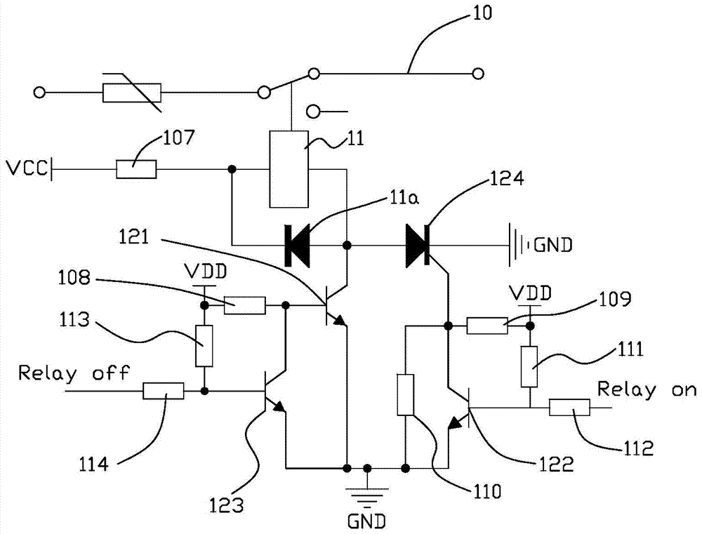
[0066] refer to image 3 , which is a circuit diagram of another specific embodiment of the aforementioned smart device control circuit 100 . Such as image 3 As shown, in this embodiment, the core control device 11 is a DC relay, and the DC relay is connected in reverse parallel with a diode 11a. That is to say, the input end of the relay is electrically connected to the cathode of the diode 11a, and the output end of the relay is electrically connected to the anode of the diode 11a. The function of the diode 11a is to prevent the counter electromotive force generated when the relay coil is energized and de-energized from causing damage to other devices. The relay input terminal is also electrically connected to the first voltage source VCC via the seventh resistor 107 , the voltage of the first voltage source VCC is 5V, for example.
[0067] The state holding circuit module 12 includes a thyristor 124 , a first transistor 121 , a second transistor 122 , and a third transi...
Embodiment 3
[0080] refer to Figure 5 , which is a circuit diagram of another specific embodiment of the aforementioned smart device control circuit 100 . Such as Figure 5 As shown, in this embodiment, the core control device 11 is a magnetic latching relay (simplified by symbol L). The characteristic of the magnetic latching relay is that after electrification, the internal magnetization becomes a permanent magnet, and it can maintain an all-in-one state according to the principle that the same poles repel each other and the opposite poles attract each other.
[0081] The state holding circuit module 12 includes a driving circuit for driving the magnetic holding relay, which includes a first input end 201 and a second input end 202, and the first input end 201 and the second input end 202 are connected to the micro control unit 13 respectively. The first I / O port (relayoff) is electrically connected to the second I / O port (relayon). The function of the drive circuit is: when the firs...
PUM
 Abstract
Description
Claims
Application Information
 - R&D
- Intellectual Property
- Life Sciences
- Materials
- Tech Scout
- Unparalleled Data Quality
- Higher Quality Content
- 60% Fewer Hallucinations
Browse by: Latest US Patents, China's latest patents, Technical Efficacy Thesaurus, Application Domain, Technology Topic, Popular Technical Reports.
© 2025 PatSnap. All rights reserved.Legal|Privacy policy|Modern Slavery Act Transparency Statement|Sitemap|About US| Contact US: help@patsnap.com