Spinneret orifice positioning and comprehensive detecting experimental apparatus for stainless steel wire rod production line

A technology of comprehensive testing and experimental equipment, applied in the direction of measuring equipment, testing of machine/structural components, instruments, etc., it can solve the problems of harsh environmental conditions on the production site, affecting the orderly production of production, and roller jamming.

Inactive Publication Date: 2010-09-15
HUZHOU VOCATIONAL TECH COLLEGE
View PDF4 Cites 0 Cited by
  • Summary
  • Abstract
  • Description
  • Claims
  • Application Information

AI Technical Summary

Problems solved by technology

Due to the gap between the roller tables, the head of the finished wire is easily planted between the roller gaps, causing the roller table to be stuck, causing the transmission motor to trip due to overcurrent, causing the wire to accumulate and produce defective products. Due to high temperature and other reasons, it is extremely difficult to handle. Affect the orderly progress of production and cause economic losses
In order to avoid this situation, it is necessary to study the operation of the laying machine to solve the problem of head positioning detection and control. However, due to the harsh environmental conditions of the production site, high temperature, high speed, noise, vibration, dust and spraying Water mist, etc., cannot carry out in-depth and detailed understanding of the operation law mechanism, so it is extremely necessary to establish a comprehensive detection experimental simulation device for the positioning of the spinning mouth to study the operation mechanism and detection methods.

Method used


Image

  • Spinneret orifice positioning and comprehensive detecting experimental apparatus for stainless steel wire rod production line
  • Spinneret orifice positioning and comprehensive detecting experimental apparatus for stainless steel wire rod production line

Examples


Embodiment Construction

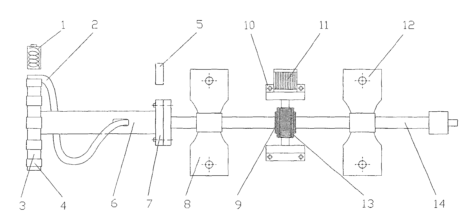
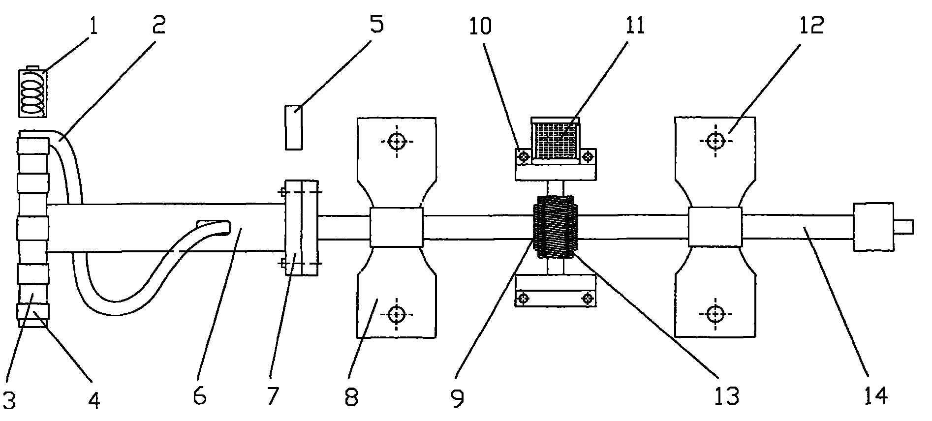
[0008] As shown in the attached figure, the comprehensive detection experiment device for the positioning of the spinning mouth of the stainless steel wire production line includes a magnetoelectric sensor 1, a spiral spinning tube 2, a circular flying disc 3, an L-shaped iron bracket 4, an optical fiber sensor 5, a hollow stainless steel tube 6, a stainless steel Flange 7, front spherical bearing supporting seat 8, worm rod 9, stepping motor supporting frame 10, stepping motor 11, rear spherical bearing supporting seat 12, turbine 13, hollow stainless steel main shaft 14, circular flying disc 3 and stainless steel pipe 6 One end is connected, the other end of the stainless steel pipe 6 is connected with the stainless steel flange 7, and one end of the spiral spinning pipe is fixed on the circular flying disc 3 through the iron bracket 4, and the hollow stainless steel main shaft 14 is sequentially provided with a front spherical bearing support seat 8, Turbine 13, rear spheric...


PUM


Abstract

The invention discloses a comprehensive detection experimental device for the positioning of spinnerules on a production line of stainless steel wire rods. A round frisbee is connected with one end of a stainless steel tube, the other end is connected with a stainless steel flange, and one end of a spiral spinning tube is fixed on the round frisbee through an iron support; a front spherical bearing support seat, a turbine and a rear spherical bearing support seat are sequentially arranged on a hollow stainless steel spindle, the turbine is engaged with a scroll bar which is connected with a step motor, and the step motor is fixed on a bearing frame of the step motor; the hollow stainless steel spindle is connected with the stainless steel flange, and the other end of the spiral spinning tube penetrates through the hollow stainless steel spindle; lines alternating between black and white are arranged on the outer circumference of the stainless steel flange, optical fiber sensors are arranged corresponding to the lines alternating between black and white on the outer circumference of the stainless steel flange, and magnetoelectric sensors are arranged on the periphery of the round frisbee. The invention can simulate the operation of production equipment, and various sensors are arranged so as to carry out experimental testing and control research in various operation states.

Description

technical field [0001] The invention relates to an experimental device for positioning detection, in particular to an experimental device for comprehensive detection of the positioning of a spinneret of a stainless steel wire production line. Background technique [0002] During the production process of the stainless steel wire production line, the wire is ejected from the spinning tube of the laying machine at a high speed of 50-150 m / s. The spinning tube is composed of a spiral tube. When spinning, the spiral tube operates at a high speed. rotate. When the rolled piece passes through the spinning helical tube, the wire rod becomes a circle with a certain radius and falls on the Stelmore roller table. Due to the gap between the roller tables, the head of the finished wire is easily planted between the roller gaps, causing the roller table to be stuck, causing the transmission motor to trip due to overcurrent, causing the wire to accumulate and produce defective products. ...

Claims


Application Information

Patent Timeline
Patent Type & Authority Patents(China)
IPC IPC(8): G01M19/00G01M99/00
Inventor 李天真曹真左希庆卢健儿
Owner HUZHOU VOCATIONAL TECH COLLEGE
Why Eureka
Try Eureka