A car fuel tank protection structure

A technology for automotive fuel tanks and protective structures, which is applied to vehicle components, the layout combined with the fuel supply of internal combustion engines, power devices, etc., can solve the problems of no guarantee, poor impact resistance, poor buffering ability, etc., to avoid unpredictable accidents Dangerous, strong impact resistance, good cushioning effect

Active Publication Date: 2018-04-27
GAC TOYOTA MOTOR
View PDF9 Cites 0 Cited by
  • Summary
  • Abstract
  • Description
  • Claims
  • Application Information

AI Technical Summary

Problems solved by technology

[0002] At present, the safety of the fuel tank of passenger cars has attracted the attention of the entire industry and the country when an accident occurs, because in an accident, once the fuel tank ruptures due to severe impact and catches fire, it will have serious consequences and even cause the car to be destroyed. The passenger car safety standard stipulates that the fuel tank must be placed behind the center of the front wheel. In the past, the industry used to arrange the fuel tank in front of the front wheel in order to occupy the least space in the luggage compartment. Now it is arranged behind the center of the front wheel and needs to be placed in the original luggage compartment. Separately draw the fuel tank compartment to ensure that the vehicle has a sufficient buffer area to ensure the safety of the fuel tank when the vehicle is subjected to a frontal collision, but this structure does not guarantee the safety of the fuel tank when the vehicle is subjected to a side collision. Yes, but the distance between the fuel tank and the sides of the vehicle body has not changed, especially now that due to the demand for cost and lightweight, more and more fuel tanks are made of plastic materials, which have weaker shock absorption capabilities, such as the patent No. 201520395731.0 , including the base assembly used to carry the fuel tank, the protective frame assembly welded on the base assembly to protect the fuel tank, and the slide rail fixed on the vehicle body. The slide rail is arranged along the width direction of the vehicle body, and the base assembly and the slide Rails form a sliding fit. Although the safety of the fuel tank is guaranteed to a certain extent, its cushioning capacity is poor, and the impact resistance is poor, so it cannot protect the fuel tank well. The fuel tank is easily damaged when an accidental impact occurs, resulting in unpredictable dangers.

Method used


Image

  • A car fuel tank protection structure
  • A car fuel tank protection structure
  • A car fuel tank protection structure

Examples


Embodiment Construction

[0016] The following will clearly and completely describe the technical solutions in the embodiments of the present invention with reference to the accompanying drawings in the embodiments of the present invention. Obviously, the described embodiments are only some, not all, embodiments of the present invention. Based on the embodiments of the present invention, all other embodiments obtained by persons of ordinary skill in the art without making creative efforts belong to the protection scope of the present invention.

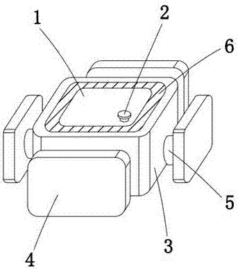
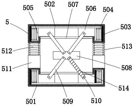
[0017] see Figure 1-5 , the present invention provides a technical solution: a car fuel tank protection structure, including a car fuel tank 1, the top of the car fuel tank 1 is provided with an oil inlet 2, through which oil is added to the car fuel tank 1, the car The outer side of the fuel tank 1 is provided with a protection box 3, and the protection box 3 plays a good role in protecting the automobile fuel tank 1. The outer side of the protection box 3 i...


PUM


Abstract

The invention discloses an automotive fuel tank protection structure. The automotive fuel tank protection structure comprises an automotive fuel tank, wherein a protective box is arranged on the outer side of the automotive fuel tank, a baffle is arranged on the outer side of the protective box and comprises a pressure resistance plate, a clamping plate is arranged on the inner side of the pressure resistance plate, and the baffle is connected with the protective box through a buffer component; the buffer component comprises a cylinder, a groove is formed in the outer wall of the cylinder, a slideway is arranged on the inner wall of the cylinder, clamp bases are arranged at the left end and right end of the slideway, a first spring is arranged on the inner side of each clamp base, a clamp block is arranged on the inner side of each first spring, and a sliding block is arranged on the inner side of each clamp block; a connecting block is arranged inside the cylinder and connected with the sliding blocks through connecting rods. Under the cooperation of the protective box, the baffle and the buffer component, the automotive fuel tank can be well buffered in an accidental collision and protected against damage, and unpredictable dangers are avoided.

Description

technical field [0001] The invention relates to the technical field of fuel tanks, in particular to an automobile fuel tank protection structure. Background technique [0002] At present, the safety of the fuel tank of passenger cars has attracted the attention of the entire industry and the country when an accident occurs, because in an accident, once the fuel tank ruptures due to severe impact and catches fire, it will have serious consequences and even cause the car to be destroyed. The passenger car safety standard stipulates that the fuel tank must be placed behind the center of the front wheel. In the past, the industry used to arrange the fuel tank in front of the front wheel in order to occupy the least space in the luggage compartment. Now it is arranged behind the center of the front wheel and needs to be placed in the original luggage compartment. Separately draw the fuel tank compartment to ensure that the vehicle has a sufficient buffer area to ensure the safety...

Claims


Application Information

Patent Timeline
Patent Type & Authority Patents(China)
IPC IPC(8): B60K15/063B60K15/073
CPCB60K15/03B60K15/063B60K15/073B60K2015/03375
Inventor 郭永利
Owner GAC TOYOTA MOTOR
Why Eureka
Try Eureka