
Socket adapter with telescopic plug

A converter and telescopic technology, applied in the base/casing, electrical components, coupling devices, etc., can solve the problems of unable to extend, unable to extend the LN pole pin, inconvenient to use, etc., and achieve the effect of high practical value

Active Publication Date: 2016-01-20
BULL GRP CO LTD
View PDF4 Cites 17 Cited by
  • Summary
  • Abstract
  • Description
  • Claims
  • Application Information

AI Technical Summary

Problems solved by technology

[0003] The purpose of the present invention is to solve the problem that the ground pole pin cannot extend with the LN pole pin after being retracted and is inconvenient to use in the retractable socket converter of the prior art, and provides a ground pole pin that can be LN pole protruding, easy-to-use receptacle converter with retractable plug
In this way, the present invention solves the problem of inconvenient use that cannot be extended with the LN pole pin after the ground pole pin is retracted in the conventional plug retractable socket converter.

Method used


Image

  • Socket adapter with telescopic plug
  • Socket adapter with telescopic plug
  • Socket adapter with telescopic plug

Examples


Embodiment 1

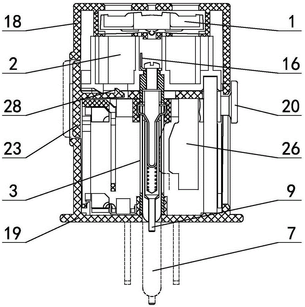
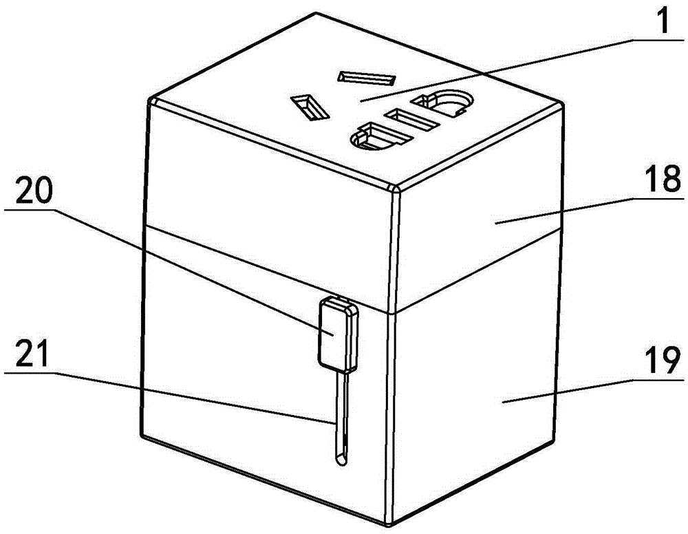
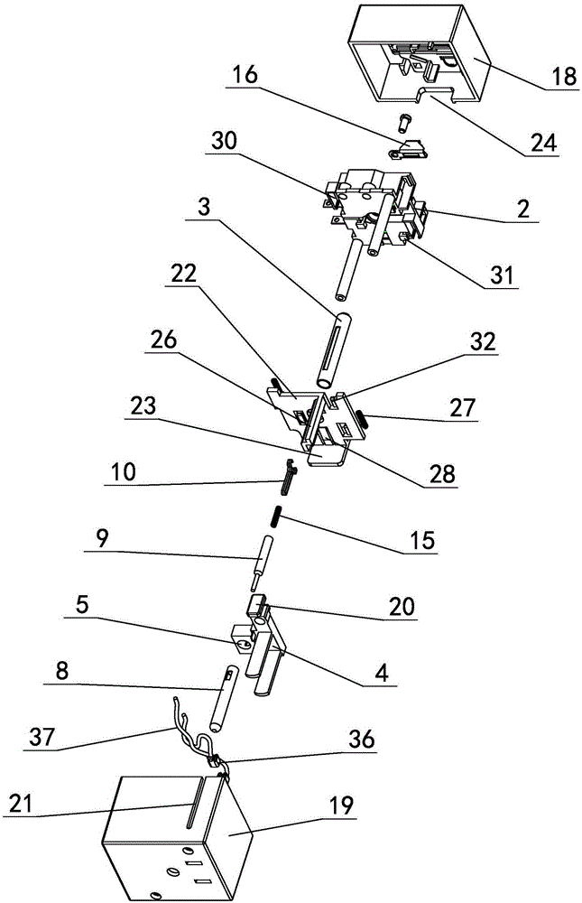
[0041] exist figure 1 , figure 2 , image 3 In the shown embodiment 1, a socket converter with a retractable plug includes a rectangular housing with a socket 1 on one side, and the housing is formed by fastening an upper housing 18 and a lower housing 19. The jack is set on the upper shell (see figure 2 ), the plug hole for accommodating the plug is set on the lower casing, and the casing is provided with an earth pole base 2 and a sliding plug base 4 (see Figure 4 Figure 5 ), the plug base is provided with a LN pole pin, the ground pole base is provided with a guide rail, the plug base is provided with a guide rail hole that slides with the guide rail and the ground pole pin 7, and the ground pole pin 7 can slide on the guide rail, One side of the sliding plug base is provided with a toggle block 20 for controlling the position of the sliding plug base (see Figure 6 ), the toggle block is located on the outer wall of the housing, and the housing is provided with a ...

Embodiment 2

[0048] Embodiment 2 The guide sleeve is in the shape of a square tube, and the ground pole pin is in the shape of a square column. The rest is the same as in the first embodiment. Embodiment 2 is applicable to a plug in which the ground pin is in the shape of a square column.

[0049] The sliding plug base used to fix the LN pole pin of the present invention can slide along the guide rail in the housing, so that the LN pole pin protrudes out of the housing or retracts from the housing; the ground pole pin is arranged on the guide sleeve and can be moved relative to the guide sleeve Sliding, the limit shrapnel is controlled between the ground pin and the plug base to determine whether the ground pin moves with the plug base. When the plug base is close to the base of the ground pole, the limit part on the limit shrapnel is located in the limit groove on the inner wall of the guide sleeve hole (see Figure 5 , Figure 17 ), at this time the ground pin is linked with the plug ba...


PUM


Abstract

The invention discloses a socket adapter with a telescopic plug. The socket adapter comprises a shell. One side of the shell is provided with a socket. A sliding-type plug base is arranged in the shell. The plug base is provided with an LN pole plug pin. The plug base is provided with a guide rail hole and a ground pole plug pin capable of sliding in the guide rail hole. An elastic sheet type limiting mechanism is disposed between the plug base and the ground pole plug pin. The plug base drives the LN pole plug pin to retract into the shell. By means of the elastic sheet type limiting mechanism between the plug base and the ground pole plug pin, the plug base and the ground pole plug pin are in the linkage state. According to the technical scheme of the invention, the ground pole plug pin can be driven by the LN pole plug pin to stretch out or retract back, so that the socket adapter is convenient in conversion and easy to carry about. Therefore, the socket adapter has a very high practical value.

Description

technical field [0001] The invention relates to the technical field of electrical connection components, in particular to a socket converter with a retractable plug. Background technique [0002] The socket converter mainly converts one form of socket into another form or multiple forms of sockets. If it is necessary to convert between the socket standards of multiple different countries, it can be called a multi-country converter. For example, convert the European standard socket to the national standard socket that meets the standard of "GB1002-2008: Single-phase plug and socket for household and similar purposes", and convert the American standard socket to the national standard socket, so that the multi-country converter can be used on the European standard and American standard sockets Provide power for electrical appliances with national standard plugs, such as mobile phone chargers and notebook power supplies with national standard plugs. Since the multi-country conv...

Claims


Application Information

Patent Timeline
Patent Type & Authority Applications(China)
IPC IPC(8): H01R31/06H01R27/00H01R13/46
Inventor 蔡梦淑
Owner BULL GRP CO LTD
Learn More