
Intelligent monitoring lamp

A lamp and intelligent technology, applied in the direction of lighting device, lighting device components, circuit layout, etc., can solve problems such as damage and loss of monitoring function, achieve good concealment, improve camera effect, and good use effect.

Inactive Publication Date: 2016-01-27
KINGSUN OPTOELECTRONIC CO LTD
View PDF6 Cites 1 Cited by
  • Summary
  • Abstract
  • Description
  • Claims
  • Application Information

AI Technical Summary

Problems solved by technology

[0002] With the development of science and technology, remote monitoring technology is very mature; but at present, remote monitoring generally completes the camera function by setting a camera or a video camera; however, the camera or video camera is very obviously set next to the monitoring scene, and it is very easy to be discovered; damage, thereby losing the monitoring function

Method used


Image

  • Intelligent monitoring lamp

Examples


Embodiment 1

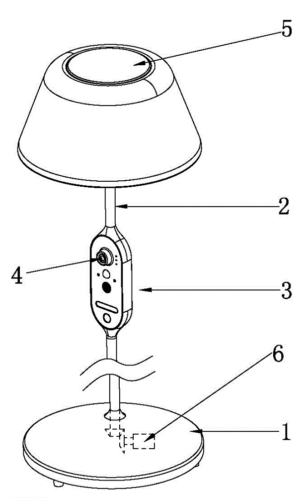
[0020] An intelligent monitoring lamp, comprising: a bracket 2, the upper end of the bracket 2 is provided with a light-emitting module 5, the middle part of the bracket 2 is provided with a control box 3, the control box 3 is provided with a camera 4, and the control box 3 is provided with a The imaging aperture of the device 4, the control circuit, the signal receiving device, and the signal transmitting device; the control circuit is signally connected with the light emitting module 5, the imaging device 4, the signal receiving device, and the signal transmitting device respectively.

[0021] When the technical solution is in use, smart devices, such as smart phones, IPADs, computers, etc., can establish a signal connection with the signal receiving device through wifi or the network, and send control signals to the control circuit, and the control circuit controls the light emitting module 5 and the camera device. 4 Working state; at the same time, the control circuit sends...


PUM


Abstract

The invention relates to the technical field of lamps, in particular to an intelligent monitoring lamp. The intelligent monitoring lamp comprises a supporting frame. A light emitting module is arranged at the upper end of the supporting frame, and a control box is arranged in the middle of the supporting frame. A camera shooting device is arranged in the control box. The control box is provided with a camera shooting hole for camera shooting of the camera shooting device, a control circuit, a signal receiving device and a signal sending device. The control circuit is in signal connection with the light emitting module, the camera shooting device, the signal receiving device and the signal sending device. Due to the fact that the control box of the lamp is provided with the camera shooting device, the lamp has the camera shooting function, and invisibility is good; besides, the lamp can provide light for camera shooting, can assist in improving the camera shooting effect and has a good use effect.

Description

technical field [0001] The invention relates to the technical field of street lamps, in particular to an intelligent monitoring lamp. Background technique [0002] With the development of science and technology, remote monitoring technology is very mature; but at present, remote monitoring generally completes the camera function by setting a camera or a video camera; however, the camera or video camera is very obviously set next to the monitoring scene, and it is very easy to be discovered; Destroyed, thereby losing the monitoring function. Contents of the invention [0003] The purpose of the present invention is to solve the deficiencies of the prior art, and provide an intelligent monitoring lamp, which can implement hidden monitoring and is easy to operate. [0004] The technical scheme adopted in the present invention is; [0005] An intelligent monitoring lamp, comprising: a bracket, the upper end of the bracket is provided with a light-emitting module, the middle ...

Claims


Application Information

Patent Timeline
Patent Type & Authority Applications(China)
IPC IPC(8): F21V23/00F21V33/00
Inventor 张政宽
Owner KINGSUN OPTOELECTRONIC CO LTD
Learn More