

camera device
A camera and functional technology, which is applied in the direction of TV, color TV parts, TV system parts, etc., can solve the problems such as the increase of correction cost, achieve the effect of fast image processing, increase the degree of freedom, and reduce the number of development man-hours
- Summary
- Abstract
- Description
- Claims
- Application Information
AI Technical Summary
Problems solved by technology
Method used
Image

Examples
no. 1 approach )
[0048] (Configuration of Camera Device 10 )
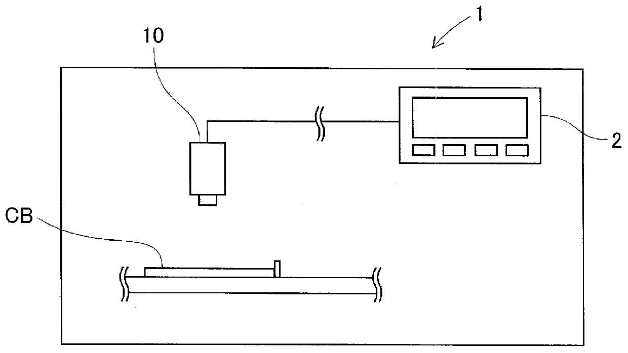
[0049] refer to Figure 1 ~ Figure 3 The camera device 10 of the first embodiment will be described. In addition, in the present embodiment, the camera device 10 is configured to be incorporated in the electronic component mounting device 1 . This electronic component mounting apparatus 1 is, for example, an apparatus for mounting a plurality of electronic components on a printed circuit board CB in a manufacturing process of an integrated circuit. Moreover, the printed circuit board CB applies solder to the mounting position of an electronic component by a paste solder printer, and conveys several mounting apparatuses sequentially, and mounts an electronic component. Thereafter, the printed circuit board CB on which the electronic components are mounted is transported to a reflow furnace and soldered to form an integrated circuit.
[0050] Such as figure 1 As shown, this electronic component mounting device 1 includes a contro...
no. 2 approach )
[0079] (Configuration of Camera Device 110 )
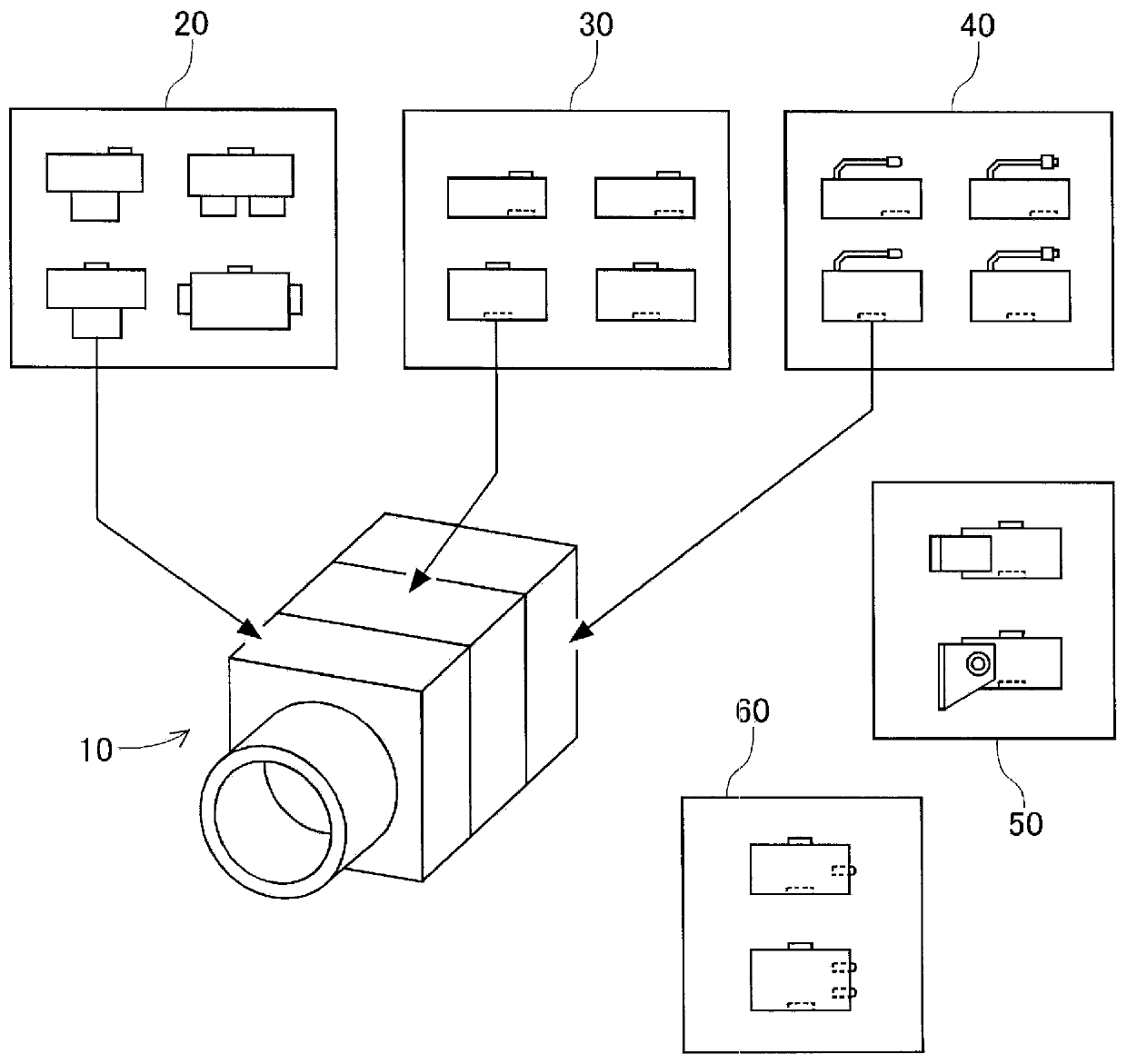
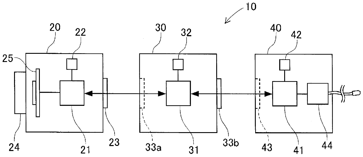
[0080] For the camera device 110 of the second embodiment, refer to Figure 4 , 5 Be explained. The configuration of the camera device 110 of the present embodiment mainly differs from that of the first embodiment in the configuration of selected modules. Other common configurations are substantially the same as those of the first embodiment, and therefore detailed descriptions are omitted. In the following, only different points will be described. In this embodiment, the camera device 110 such as Figure 4 As shown, one camera module 120 and one external communication module 140 are selected from among three or more modules having different functions, and are detachably connected to each other.
[0081] The camera module 120 is a module that captures a subject to obtain image data. Such as Figure 4 As shown, the camera module 120 has a PLD 121 , a memory unit 22 , a connection unit 123 , a lens unit 24 , and an image sens...
no. 3 approach )
[0091] (Configuration of Camera Device 210 )
[0092] For the camera device 210 of the third embodiment, refer to Figure 6 Be explained. The camera device 210 of the present embodiment differs from the first embodiment mainly in that a predetermined module constituting the camera device 210 is configured by connecting a plurality of sub-modules. Other general configurations are substantially the same as those of the first embodiment, and therefore detailed descriptions are omitted. In the following, only the points of difference will be described. In this embodiment, the camera device 210 such as Figure 6 As shown, one each of the camera module 20, the image processing module 230, and the external communication module 40 is selected from three or more modules having different functions, and these are detachably connected to form a configuration. Here, the camera module 20 and the external communication module 40 are the same as those of the first embodiment, and thus det...
PUM
 Abstract
Description
Claims
Application Information