Microphone type television direct transmission device

A live TV and microphone technology, applied in electrical components, image communication, selective content distribution, etc., can solve the problems of video signals that cannot transmit images, cannot be used with TV sets, and cannot be used for TV screen performances, etc.

Inactive Publication Date: 2016-11-23
李建刚
View PDF0 Cites 0 Cited by
  • Summary
  • Abstract
  • Description
  • Claims
  • Application Information

AI Technical Summary

Problems solved by technology

[0002] Since the end of the 19th century until now, all kinds of commonly used wired and wireless FM microphone products can only transmit the audio signal of the sound, but not the video signal of the image, so people can't use this kind of

Method used


Image

  • Microphone type television direct transmission device
  • Microphone type television direct transmission device
  • Microphone type television direct transmission device

Examples


Embodiment 1

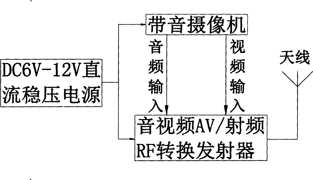
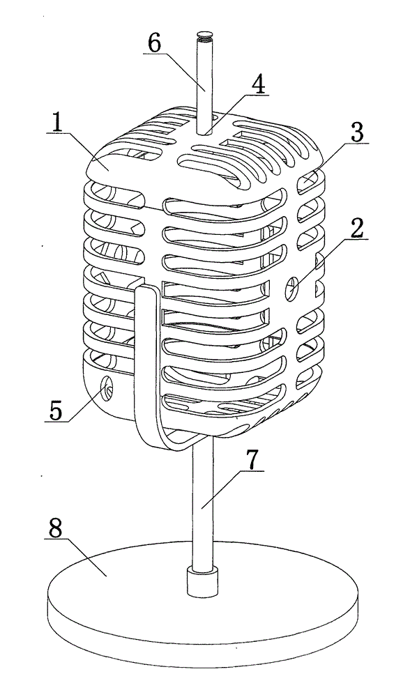
[0020] like figure 1 and figure 2 Shown, a kind of microphone type TV live broadcast device comprises microphone shell 1, is located at the CCD video camera with sound in the microphone shell 1 and audio-video AV\radio frequency RF conversion transmitter, is installed in the antenna 6 on the microphone shell 1 outer wall and is respectively The power supply of the CCD camera with sound and the AV / radio frequency RF conversion transmitter of the audio and video, wherein, a sound pickup hole 3 and a camera hole 2 are provided on the microphone shell, and the camera lens of the CCD camera with sound is directly facing the Camera hole 2 is provided with, and the audio frequency output end and the video output end of described sound-band CCD camera are respectively connected the audio frequency input end and the video input end of described audio and video AV\radio frequency RF conversion transmitter, and described audio frequency AV\radio frequency RF conversion The signal outpu...

Embodiment 2

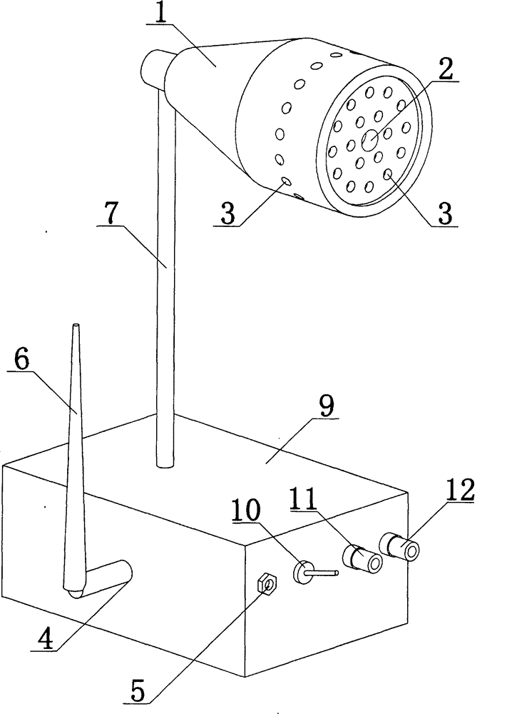
[0026] The difference between embodiment 2 and embodiment 1 is: as figure 1 and image 3 Shown, a kind of microphone type TV live broadcast device comprises microphone housing 1, the base box 9 that communicates with described microphone housing 1, CCD camera with sound, audio and video AV\ radio frequency RF conversion transmitter, antenna 6 and described respectively The power supply for the CCD camera with sound and the AV / radio frequency RF conversion transmitter of the audio and video; Located in the base box 9, the antenna 6 is installed on the base box 9, the microphone shell 1 is provided with a sound pickup hole 3 and a camera hole 2, and the lens of the CCD camera with sound is directly facing the Described camera hole 2 is provided with, and the audio frequency output end and the video output end of described sound-band CCD camera are respectively connected the audio frequency input end and the video input end of described audio and video AV\radio frequency RF conv...

Embodiment 3

[0029] The difference between embodiment 3 and embodiment 1, 2 is: as Figure 4 Shown, described CCD camera with sound comprises CCD camera and the microphone that has audio amplifier circuit, the video output end of CCD camera connects the video input end of described audio-video AV\radio frequency RF conversion transmitter, the audio frequency output of described microphone The end is connected to the audio input end of the audio-video AV\radio frequency RF conversion transmitter. The advantage of this design is that the audio amplifier can enhance the sound pickup effect of the microphone.


PUM

PropertyMeasurementUnit
Center frequencyaaaaaaaaaa

Abstract

The invention provides a microphone type television direct transmission device, comprising a microphone housing, an audio CCD (Charge Coupled Device) camera and an audio-video (AV)/ radio-frequency (RF) conversion transmitter which are arranged in the microphone housing, an antenna installed on the outer wall of the microphone housing, and a power supply for supplying power to the audio CCD camera and the AV/RF conversion transmitter respectively, wherein the microphone housing is provided with a pickup hole and a camera hole, and a lens of the CCD is opposite to the camera hole. The microphone type television direct transmission device has the advantages that the design is scientific and the device has a camera function and can wirelessly transmit audio-video signals to a television.

Description

technical field [0001] The invention relates to a live TV device, in particular to a microphone type live TV device. Background technique [0002] Since the end of the 19th century until now, all kinds of commonly used wired and wireless FM microphone products can only transmit the audio signal of the sound, but not the video signal of the image, so people can't use this kind of microphone to connect to the TV at all. Screens for performances, because they can only be used with amplifiers and FM radios, but cannot be used with televisions, so they cannot be used for live television broadcasts that have both images and sounds for televisions. [0003] In order to solve the above existing problems, people have been seeking an ideal technical solution. Contents of the invention [0004] The object of the present invention is to address the deficiencies of the prior art, thereby providing a microphone-type television live broadcast device with a scientific design, a camera fu...

Claims


Application Information

Patent Timeline
IPC IPC(8): H04N21/41
Inventor 李建刚
Owner 李建刚
Why Eureka
Try Eureka