
An anti-bias circuit

An anti-bias circuit and contrast circuit technology, applied in arc welding equipment, manufacturing tools, welding equipment, etc., can solve the problem of high comprehensive cost of the bias magnetic treatment method, achieve easy popularization and use, avoid the influence of bias magnetic, and process costs. low effect

Inactive Publication Date: 2017-09-08
永康市帝普特科技有限公司
View PDF7 Cites 0 Cited by
  • Summary
  • Abstract
  • Description
  • Claims
  • Application Information

AI Technical Summary

Problems solved by technology

[0006] In view of the shortcomings of the prior art above, the purpose of the present invention is to provide an anti-bias circuit, which aims to solve the problem of high comprehensive cost of the bias treatment method in the prior art

Method used


Image

  • An anti-bias circuit

Examples


Embodiment Construction

[0026] The invention provides an anti-bias circuit. In order to make the object, technical solution and effect of the present invention more clear and definite, the present invention will be further described in detail below with reference to the accompanying drawings and examples. It should be understood that the specific embodiments described here are only used to explain the present invention, not to limit the present invention.

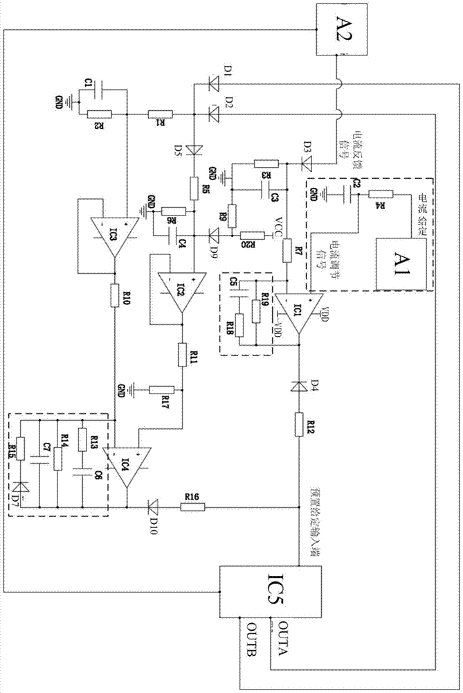
[0027] Such as figure 1 Shown is an anti-bias circuit of a specific embodiment of the present invention.

[0028] The anti-bias circuit includes a first comparison circuit, an integration circuit that outputs a current regulation signal, a feedback circuit that outputs a corresponding current feedback signal according to the bias condition, and a power chip.

[0029] The first comparison circuit receives the current adjustment signal output by the integration circuit and the current feedback signal output by the feedback circuit, and compares th...


PUM


Abstract

The invention provides an anti-bias circuit. The anti-bias circuit comprises a first comparison circuit, an integral circuit for outputting current regulation signals, a feedback circuit for outputting corresponding current feedback signals according to the bias condition and a power supply chip. The first comparison circuit receives the current regulation signals output by the integral circuit and the current feedback signals output by the feedback circuit, compares the current regulation signals with the current feedback signals and then outputs corresponding first level signals. The preset given input end of the power supply chip receives the first level signals and regulates the width of signals output by pulses according to the first level signals. The anti-bias circuit can automatically regulate the width of pulse signals output by the power supply chip according to the specific conditions such as bias or saturation, so that the bias influence is avoided; the anti-bias circuit is low in processing cost and convenient to use and popularize.

Description

technical field [0001] The invention relates to the technical field of inverter circuits, in particular to an anti-bias circuit. Background technique [0002] The inverter arc welding power supply has basically replaced the traditional industrial frequency transformer inverter voltage in the market at present, because it has a series of advantages such as high conversion efficiency, small size, light weight, and can realize fine control, etc., in some places that require frequent movement The occasions where it is used are favored by customers, such as outdoor billboard welding, door and window installation, etc. The market prospect is broad, but because the product threshold is low, many companies are crowded, resulting in the current market competition pressure and cost pressure are increasing, because the contest between cost and reliability is becoming more and more obvious. [0003] Among them, magnetic bias is a very common phenomenon in inverter circuits. Due to dev...

Claims


Application Information

Patent Timeline
Patent Type & Authority Patents(China)
IPC IPC(8): H02M7/48B23K9/10
CPCB23K9/10
Inventor 殷杰熊怡军舒展鹏
Owner 永康市帝普特科技有限公司
Learn More