Sand mold molding device and sand mold molding methods
A sand mold, non-parting technology, applied in molding machines, manufacturing tools, casting and molding equipment, etc., can solve the problem of parting surface sand mold non-parting surface sand mold compactness moderate, good air permeability, can not guarantee the parting surface sand mold enough The problems of compactness, the sand mold on the parting surface is not compact enough and air permeability, etc., to achieve the effect of good compactness and uniformity, not easy to drop the molding sand, and moderate compactness.
- Summary
- Abstract
- Description
- Claims
- Application Information
AI Technical Summary
Problems solved by technology
Method used
Image

Examples
Embodiment 1
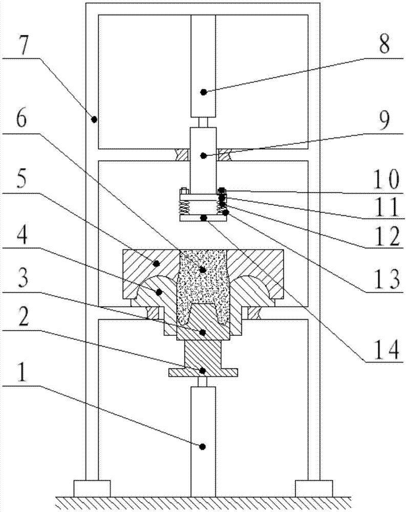
[0036] refer to figure 1, The sand molding device of this embodiment includes a mold 5, a fixed template 4, a movable template 3 and a pressing rod mechanism. The mold 5 and the fixed template 4 are stacked up and down, and the mold 5 is arranged on the fixed template 4 . The mold 5 has a first inner cavity, the fixed plate 4 has a second inner cavity, and the first inner cavity communicates with the second inner cavity. The movable template 3 is movably and form-fittingly inserted in the second cavity of the fixed template 4 from below, that is, the movable template 3 can slide in the second cavity, and during the sliding process, the movable template 3 The initial position is lower than the parting surface of the fixed template 4 and the mold 5 at a certain height, and the side wall of the movable template 3 is always in contact with the inner cavity surface of the second inner cavity, so that the inner cavity surface of the first inner cavity of the mold 5, The inner surf...
Embodiment 2
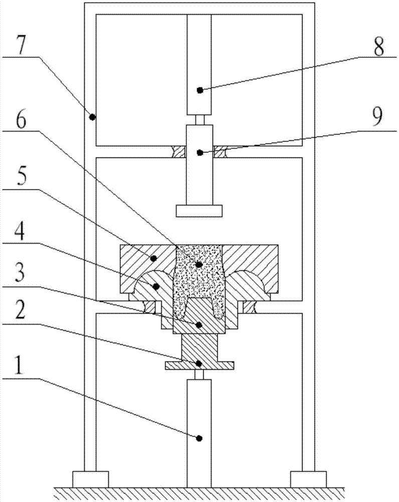
[0069] refer to figure 2 , in this embodiment, the difference from Embodiment 1 lies in the structure of the pressing rod mechanism.
[0070] Specifically, in this embodiment, the pressure rod mechanism includes a pressure rod 9 and a hydraulic cylinder. The maximum pressure value of the hydraulic cylinder is adjustable. The hydraulic cylinder drives the pressure rod 9 to move up and down and controls the pressure rod 9 to exert a controllable pressure.
[0071]When the pressure rod 9 just presses down on the sand mold 6, the resistance that the pressure rod 9 bears is less than the maximum pressure value of the hydraulic cylinder, and the pressure of the hydraulic cylinder increases with the resistance of the pressure rod 9; when the sand mold 6 reaches a certain tightness During solidification, the resistance of the pressure rod 9 increases to the maximum pressure value of the hydraulic cylinder, and the overflow valve of the oil circuit of the hydraulic cylinder begins to ...
Embodiment 3
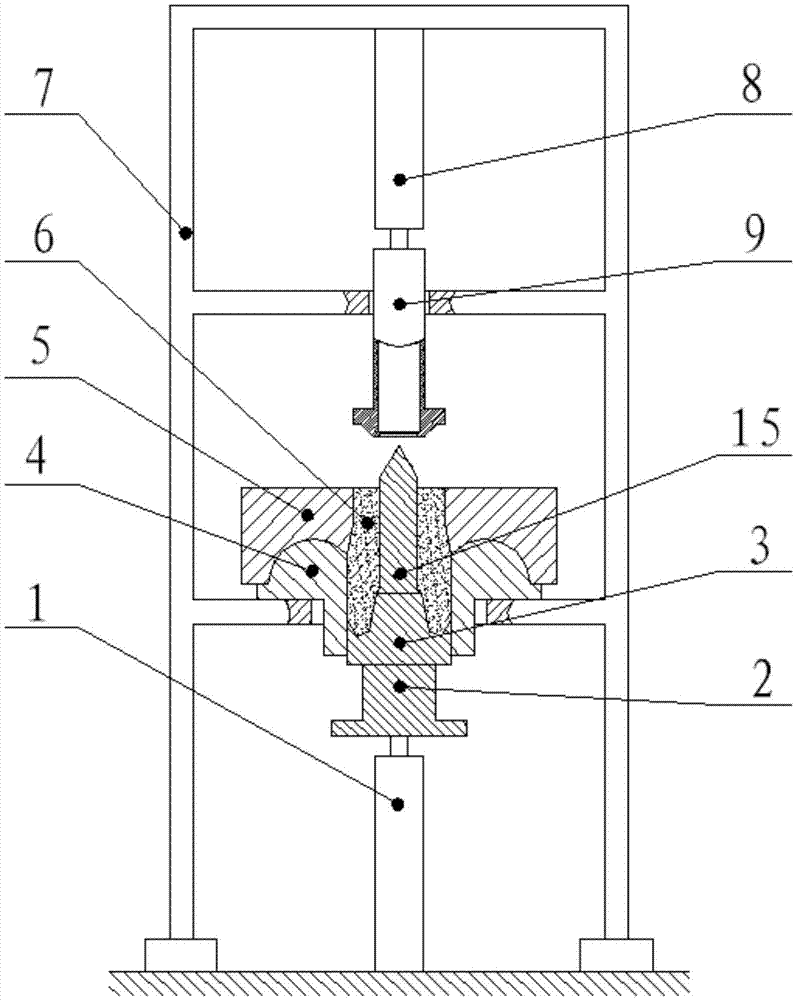
[0087] refer to image 3 , in this embodiment, the difference from Embodiment 2 is that a sand guide rod 15 is also provided on the movable formwork 3, and a hole for accommodating the sand guide rod 15 is provided in the pressure rod 9, and the hole and the sand guide rod 15 to realize the compaction of the sprue mouth sand mold 6.
[0088] It can be understood that in this embodiment, the movable formwork 3, the positioning part 2, the sand guide rod 15 and the fixed formwork 4 constitute a split formwork
[0089] The above-mentioned movable template 3 is used to apply pressure evenly to the lower sand mold 6, so that the sand mold 6 on the entire parting surface is sufficiently compact, effectively reducing the sand inclusion defects of the ball casting; Controlled pressurization, and the sand guide rod 15 and the perforated pressure rod 9 are compacted to form the sand mold 6 sprue, so that the entire upper sand mold 6 has moderate compactness and good air permeability, e...
PUM
 Abstract
Description
Claims
Application Information
 - R&D
- Intellectual Property
- Life Sciences
- Materials
- Tech Scout
- Unparalleled Data Quality
- Higher Quality Content
- 60% Fewer Hallucinations
Browse by: Latest US Patents, China's latest patents, Technical Efficacy Thesaurus, Application Domain, Technology Topic, Popular Technical Reports.
© 2025 PatSnap. All rights reserved.Legal|Privacy policy|Modern Slavery Act Transparency Statement|Sitemap|About US| Contact US: help@patsnap.com