Novel rotary shaft structure

A rotating shaft structure and a new type of technology, applied in pivot connections, lighting devices, components of lighting devices, etc., can solve problems such as increased labor costs, short service life, friction noise, etc., and achieve the effect of adjusting the hand feeling experience.

Active Publication Date: 2016-04-06
DONGGUAN JIAMENG LIGHTING TECH
View PDF5 Cites 1 Cited by
  • Summary
  • Abstract
  • Description
  • Claims
  • Application Information

AI Technical Summary

Problems solved by technology

However, after the device is used for a long time, the limit ring will become loose, and friction noise will appear when the limit ring is loose and then rotated.
[0004] This type of shaft has a simple structure, but its service life is not long, and there will be friction noise during rotation. If necessary, lubricants should be added to eliminate noise, which will increase labor costs and reduce the high-end performance of the product.

Method used


Image

  • Novel rotary shaft structure
  • Novel rotary shaft structure
  • Novel rotary shaft structure

Examples


Embodiment 1

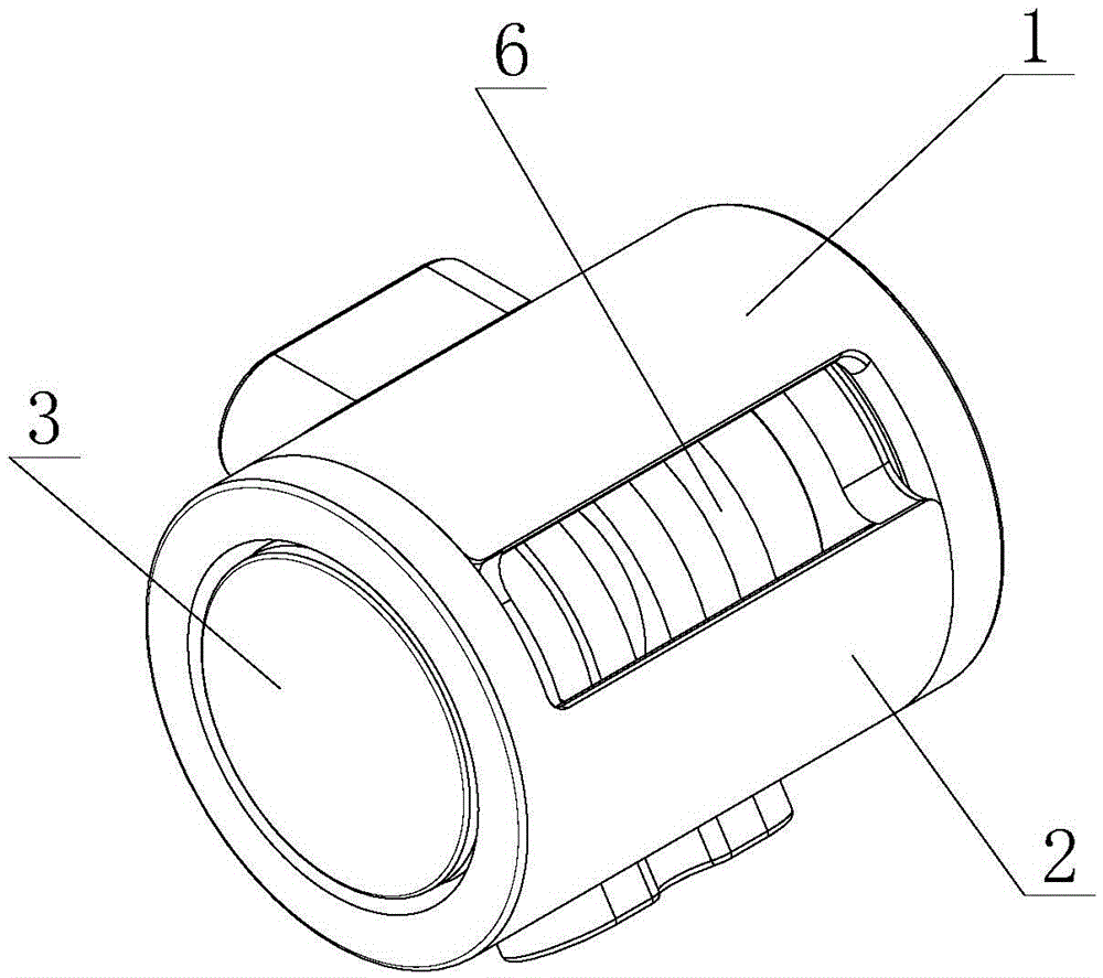
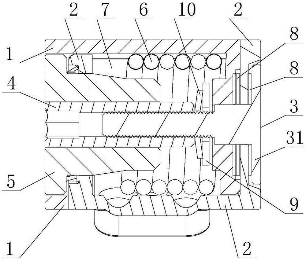
[0027] A new shaft structure is provided in this embodiment, such as Figure 1-2 As shown, it includes an upper rod fixed shaft 1, a lower rod fixed shaft 2, a tightening screw 3 passing through the upper rod fixed shaft 1 and the lower rod fixed shaft 2 in turn, an internally threaded shaft 4 cooperating with the tightened screw 3 and locking pin 5;

[0028] At least one end of the upper rod fixed shaft 1 or the lower rod fixed shaft 2 is located in the lower rod fixed shaft 2 or the upper rod fixed shaft 1, and the upper rod fixed shaft 1 and the lower rod fixed shaft 2 can rotate with each other without axial displacement change , the end of the lower rod fixed shaft 2 away from the tightening screw 3 is also provided with a locking groove 21 that matches the locking pin 5; the upper rod fixed shaft 1 or the lower rod fixed shaft 2 is provided with a spring 6, and the lower rod is fixed A rotation groove 7 is provided on the side wall of the shaft 2; one end of the spring ...

Embodiment 2

[0031] A new shaft structure is provided in this embodiment, such as Figure 1-2 As shown, it includes an upper rod fixed shaft 1, a lower rod fixed shaft 2, a tightening screw 3 passing through the upper rod fixed shaft 1 and the lower rod fixed shaft 2 in turn, an internally threaded shaft 4 cooperating with the tightened screw 3 and Locking pin 5.

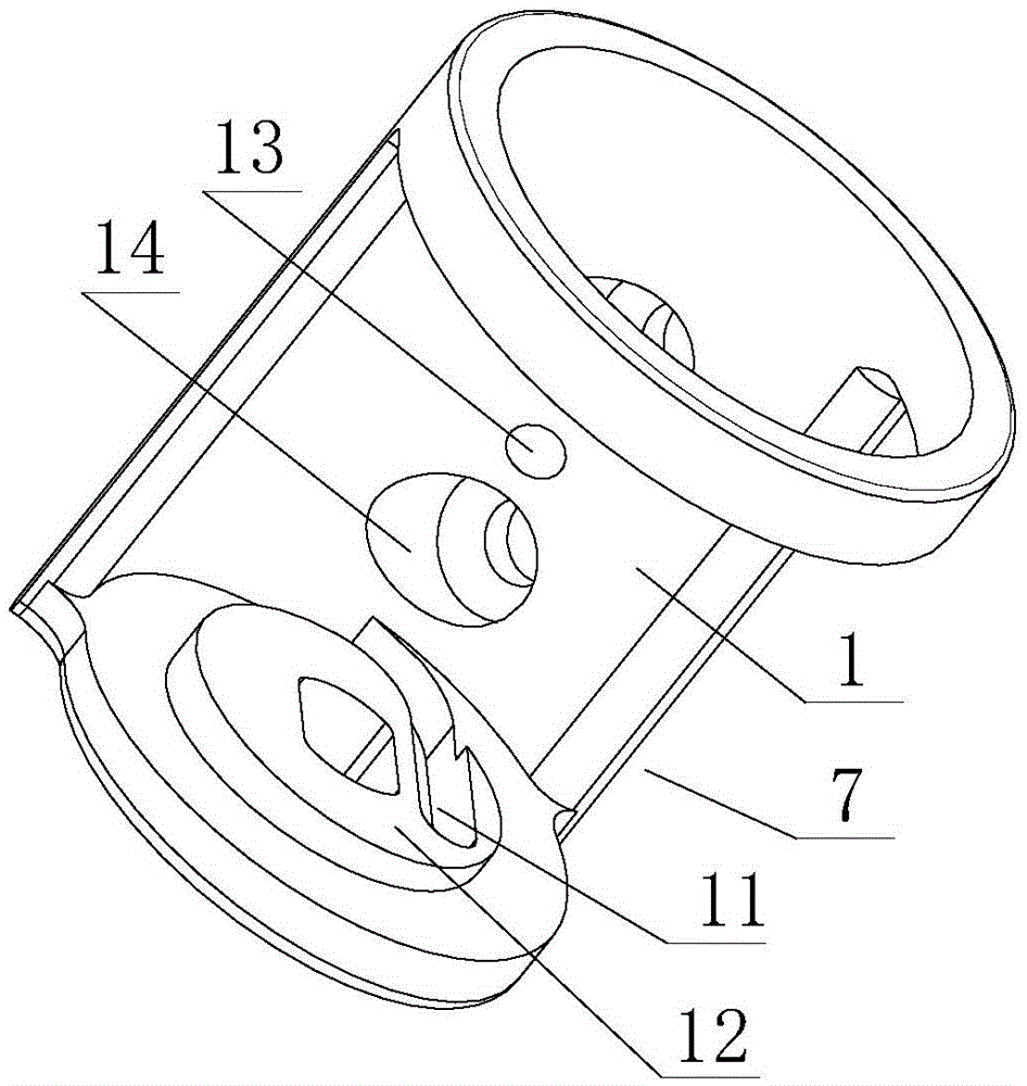
[0032] like Figure 3-4 As shown, the side walls of the upper rod fixed shaft 1 and the lower rod fixed shaft 2 are provided with a rotation groove 7, and one end of the upper rod fixed shaft 1 is located in the lower rod fixed shaft 2, and the upper rod fixed shaft 1 is fixed with the lower rod The shafts 2 are mutually rotatable and coaxial, and the other end of the upper rod fixed shaft 1 is located outside the lower rod fixed shaft 2; the same side of the upper rod fixed shaft 1 and the lower rod fixed shaft 2 are equipped with Tighten the through hole of the screw 3, and tighten the screw 3 through one end of the upper ro...

Embodiment 3

[0041] The difference with embodiment 2 in this embodiment is:

[0042] The upper rod fixed shaft 1 is located in the lower rod fixed shaft 2, and the upper rod fixed shaft 1 and the lower rod fixed shaft 2 are provided with a rotation groove 7, the spring 6 is located in the upper rod fixed shaft 1, and one end of the spring 6 is fixed to the upper rod The shaft 1 is fixed, and the other end is fixed with the locking pin 5.

[0043] Other structures are the same as those in Embodiment 2, and will not be repeated here.


PUM


Abstract

The invention relates to the technical field of LED lamp illumination, in particular to a novel rotary shaft structure for rotating an LED lamp. The novel rotary shaft structure comprises an upper rod fixing shaft, a lower rod fixing shaft, a clamping screw, an inner thread shaft matched with the clamping screw and a locking pin. At least one end of the upper / lower rod fixing shaft is located in the lower / upper rod fixing shaft, and the upper rod fixing shaft and the lower rod fixing shaft can relatively rotate. A locking groove matched with the locking pin is further formed in the end, away from the clamping screw, of the lower rod fixing shaft. Due to the fact that the spring is arranged, a user can adjust the angle between an upper rod and a lower rod by ligh A spring is arranged in one upper / lower rod fixing shaft, and a rotary groove is formed in the side wall of the lower rod fixing shaft. The two ends of the spring are fixedly connected with the upper rod fixing shaft and the lower rod fixing shaft respectively. tly pressing or lifting the upper rod when adjusting the angle between the upper rod and the lower rod of the lamp. The need for easily rotating and adjusting heavy lamps is met, and meanwhile the user has good adjusting hand feeling experience.

Description

technical field [0001] The invention relates to the technical field of LED lamp lighting, in particular to a novel rotating shaft structure for LED lamp rotation. Background technique [0002] Due to the continuous development and innovation of LED technology, people's pursuit of novelty and high-end household lighting products is also getting higher and higher. At present, the common rotatable LED desk lamps, arm lamps, floor lamps, corner lamps, etc., all of the above-mentioned lamps use the rotating shaft structure, but the rotating shaft structure in the prior art is complicated, and most of them are fixed in the form, requiring specific tools to use. It can be installed only after the body is deformed. The process is more complicated and the damage to the body is greater. [0003] Chinese patent document CN104791371A novel shaft structure discloses a shaft device for LED lamps, which includes a shaft part, a rotating part, a shaft core and a limit ring. The shaft core ...

Claims


Application Information

Patent Timeline
IPC IPC(8): F16C11/04
CPCF16C11/04F21V21/10F21V21/14
Inventor 陈胜雄
Owner DONGGUAN JIAMENG LIGHTING TECH
Why Eureka
Try Eureka