
Camera module position change method and system, and camera module

A camera module and camera technology, applied in the camera field, can solve problems such as poor user experience and inability to change the structure of the camera module, and achieve the effect of improving the experience

Inactive Publication Date: 2018-04-20
TRULY OPTO ELECTRONICS
View PDF6 Cites 1 Cited by
  • Summary
  • Abstract
  • Description
  • Claims
  • Application Information

AI Technical Summary

Problems solved by technology

[0003] Electronic camera modules in the prior art are mainly connected and fixed by PCB boards or brackets. Due to the characteristics of the materials of the PCB board and the bracket itself, the structural changes of the camera module cannot be realized, and the user experience is poor.

Method used

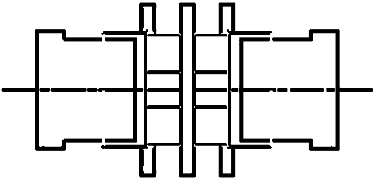

Image

  • Camera module position change method and system, and camera module
  • Camera module position change method and system, and camera module
  • Camera module position change method and system, and camera module

Examples


Embodiment Construction

[0036] The following will clearly and completely describe the technical solutions in the embodiments of the present invention with reference to the accompanying drawings in the embodiments of the present invention. Obviously, the described embodiments are only some, not all, embodiments of the present invention. Based on the embodiments of the present invention, all other embodiments obtained by persons of ordinary skill in the art without creative efforts fall within the protection scope of the present invention.

[0037] The embodiment of the invention discloses a method for changing the position of a camera module, which realizes the position change of each camera in the camera module.

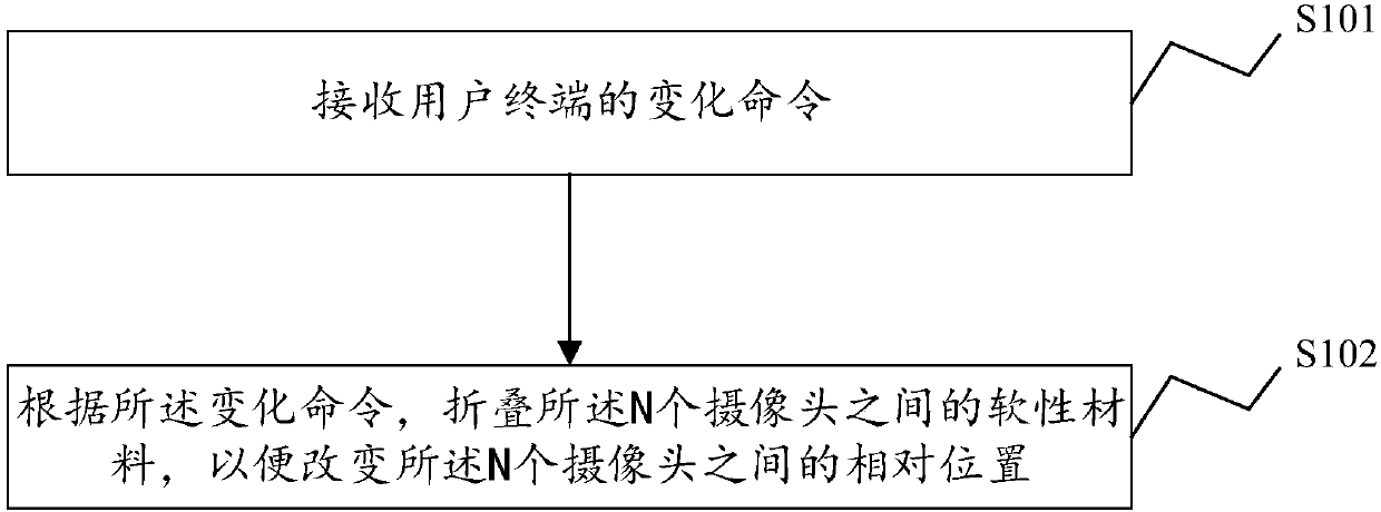
[0038] see figure 1 , a flowchart of a method for changing the position of a camera module disclosed in an embodiment of the present invention, as shown in figure 1 As shown, it is used to change the relative positions between the N cameras in the camera module, where N is an integer great...


PUM


Abstract

The invention discloses a camera module position change method used for changing a relative position between N cameras in the camera module, wherein N is an integer greater than 1. The method comprises the following steps of receiving a change command of a user terminal; and folding a soft material between the N cameras according to the change command in order to change the relative position between the N cameras. According to the camera module position change method disclosed by the invention, cameras in the camera module are connected through the soft material, the distance or the position can be adjusted through the soft material between the cameras, the position change of each camera in the camera module is realized, and the experience feeling of the user is improved. The invention further discloses a camera module position change system, the camera module and a computer readable storage medium, and the technical effect can be achieved.

Description

technical field [0001] The present invention relates to the field of camera technology, and more specifically, to a method and system for changing the position of a camera module, a camera module, and a computer-readable storage medium. Background technique [0002] At present, most mobile devices, such as mobile phones and tablet computers, are equipped with camera modules, which can realize the conversion between optical signals and electrical signals, record and save image information through the camera modules, so as to realize the functions of taking pictures and photographing. [0003] Electronic camera modules in the prior art are mainly connected and fixed by PCB boards or brackets. Due to the characteristics of the materials of the PCB board and brackets, structural changes of the camera module cannot be realized, and the user experience is poor. [0004] Therefore, how to change the position of each camera in the camera module is a problem to be solved by those ski...

Claims


Application Information

Patent Timeline
Patent Type & Authority Applications(China)
IPC IPC(8): H04N5/225
CPCH04N23/50H04N23/57
Inventor 王军伟
Owner TRULY OPTO ELECTRONICS
Learn More