
Welding mechanism

A welding mechanism and welding electrode technology, applied in welding equipment, resistance welding equipment, resistance electrode holder, etc., can solve the problem of long welding cycle

Pending Publication Date: 2020-12-22
合兴汽车电子(太仓)有限公司
View PDF0 Cites 1 Cited by
  • Summary
  • Abstract
  • Description
  • Claims
  • Application Information

AI Technical Summary

Problems solved by technology

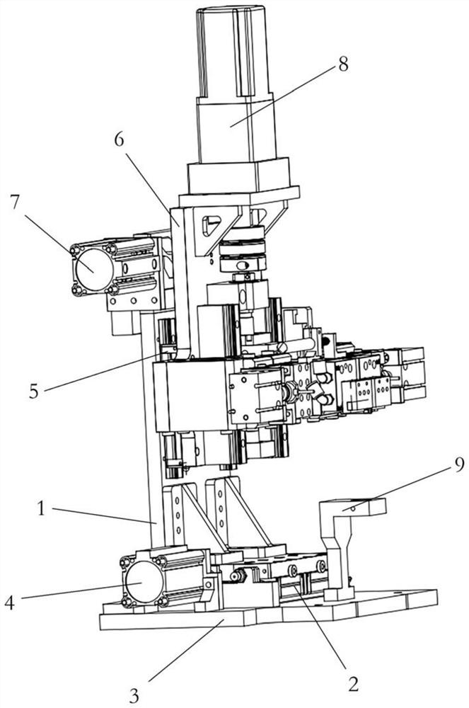
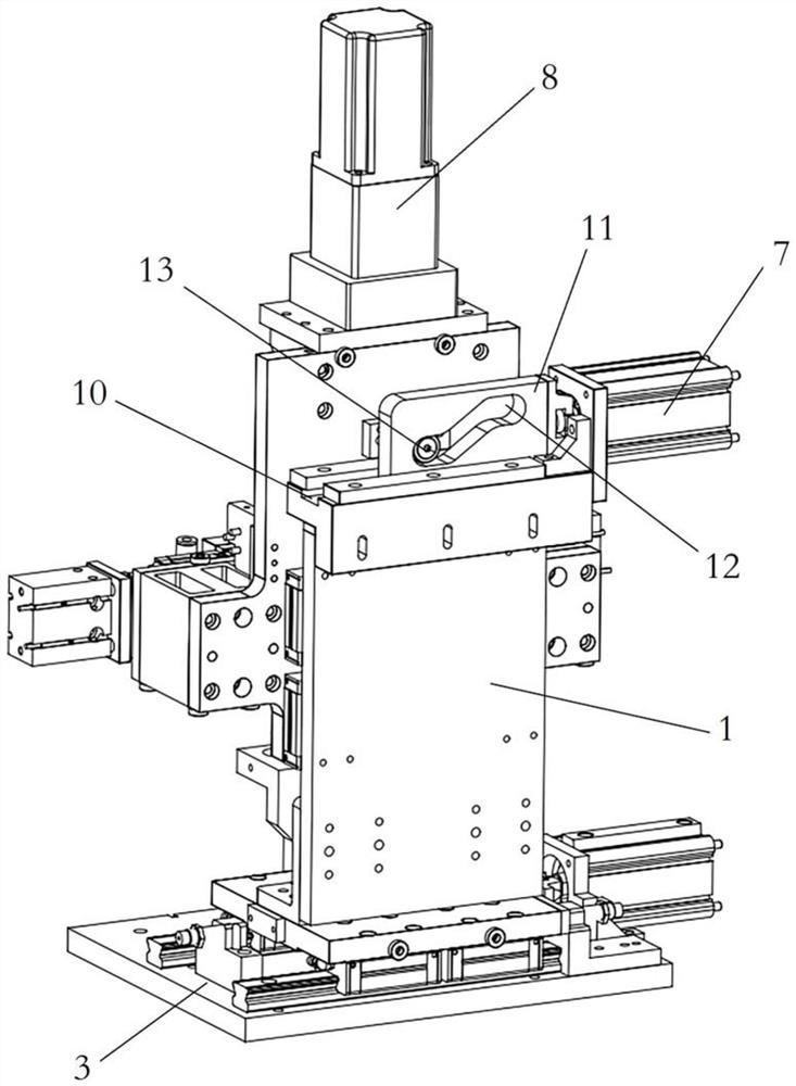
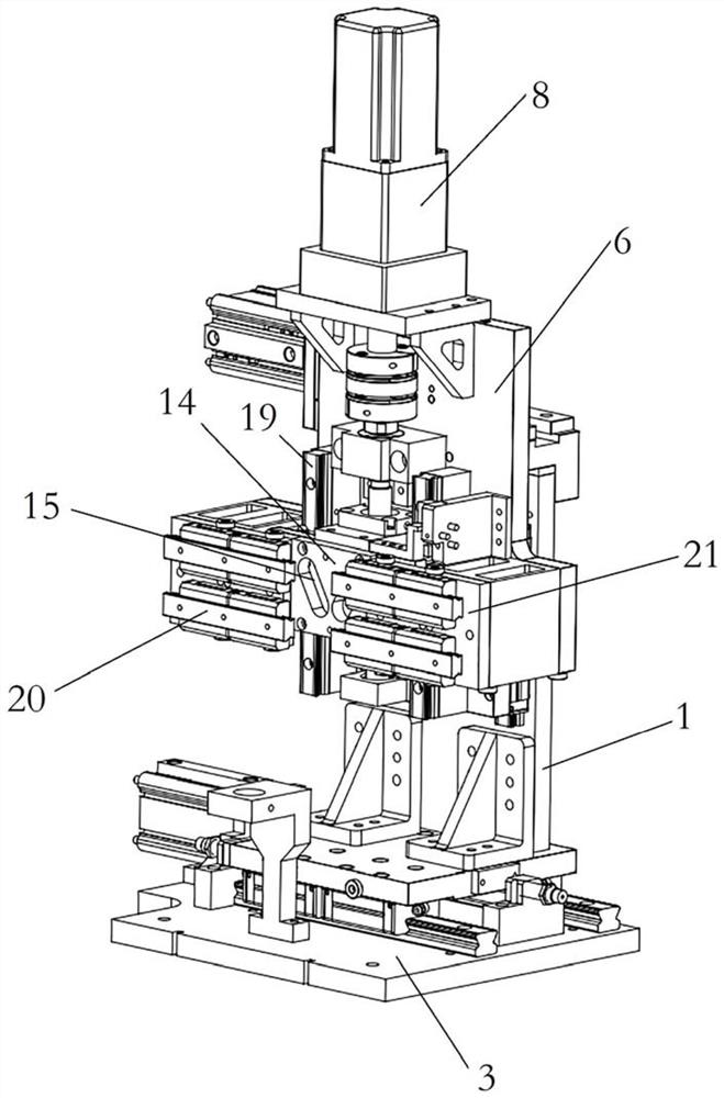
[0005] Therefore, the technical problem to be solved by the present invention is to overcome the defect that the welding cycle is too long in the process of welding two fork terminals in the prior art, thereby providing a welding mechanism

Method used


Image

  • Welding mechanism
  • Welding mechanism
  • Welding mechanism

Examples


Embodiment Construction

[0046] The technical solutions of the present invention will be clearly and completely described below in conjunction with the accompanying drawings. Apparently, the described embodiments are part of the embodiments of the present invention, but not all of them. Based on the embodiments of the present invention, all other embodiments obtained by persons of ordinary skill in the art without making creative efforts belong to the protection scope of the present invention.

[0047] In the description of the present invention, it should be noted that the terms "center", "upper", "lower", "left", "right", "vertical", "horizontal", "inner", "outer" etc. The indicated orientation or positional relationship is based on the orientation or positional relationship shown in the drawings, and is only for the convenience of describing the present invention and simplifying the description, rather than indicating or implying that the referred device or element must have a specific orientation, ...


PUM


Abstract

The invention provides a welding mechanism, and belongs to the technical field of welding. The welding mechanism comprises a support frame, a first driving device, a mounting plate, a second driving device, a welding assembly and a weldment mounting seat. According to the welding mechanism, a to-be-welded part is fixed to the weldment mounting base, the second driving device is started to drive the mounting plate to drive the welding assembly to move upwards, the to-be-welded part is avoided, the first driving device is started, and the support frame is pushed to horizontally move along an operation platform, so that a welding motor moves from the upper part of one fork port terminal to the upper part of the other fork port terminal. The second driving device is started again to drive themounting plate to drive the welding assembly to move downwards, so that a welding electrode abuts against the fork opening terminals of the to-be-welded part, and finally the position of the welding electrode between the two fork opening terminals is changed.

Description

technical field [0001] The invention relates to the technical field of electrical component welding, in particular to a welding mechanism. Background technique [0002] Welding, also known as welding, is a manufacturing process and technique that uses heat, high temperature, or pressure to join metal or other thermoplastic materials such as plastics. [0003] The terminal is an accessory that acts as a switch in various types of electronically controlled power distribution equipment, complete sets of devices, multi-circuit meter boxes and combined terminal electrical boxes. Among them, the fork terminal is a relatively common one. The fork terminal generally includes a Y-shaped fork part and a conductive connection part. Usually, a welding mechanism is used to weld and fix the conductive connection part and the wire to realize the connection between the fork terminal and the wire. connect. [0004] Usually, there are two fork terminals on an electrical structure. During th...

Claims


Application Information

Patent Timeline
Patent Type & Authority Applications(China)
IPC IPC(8): B23K11/02B23K11/36B23K11/31
CPCB23K11/02B23K11/36B23K11/31B23K2101/36
Inventor 黄伟季扬超
Owner 合兴汽车电子(太仓)有限公司
Learn More