Light source assembly for projection system

A light source component and projection system technology, applied in optics, instruments, projection devices, etc., can solve problems such as light waste, inability to enter the system, and bulb brightness attenuation, and achieve the effects of improving light efficiency, increasing light efficiency, and increasing power

Active Publication Date: 2016-04-13
SHENZHEN HUOLE TECH DEV CO LTD
View PDF6 Cites 9 Cited by
  • Summary
  • Abstract
  • Description
  • Claims
  • Application Information

AI Technical Summary

Problems solved by technology

[0003] First of all, the service life of the bulb can only be maintained for a few thousand hours, and as time goes on, the brightness of the bulb will decay. In this way, consumers need to replace the bulb when other parts of the projector except the bulb can still be used normally. , which brings additional expenses; secondly, because the bulb is a gas light source, it needs to be driven by a high-voltage driver board, and it cannot be turned on immediately, which is extremely inconvenient in practice; thirdly, the ultraviolet light and infrared light emitted by the bulb are harmful to the surrounding environment and radiation. Components will cause damage. In addition, the high-pressure mercury element in the bulb itself does not meet environmental protection requirements. For these reasons, the use of solid light sources to replace bulbs has always been a research topic in this industry.
[0004] As a solid light source, light-emitting diodes have the characteristics of long life, rich colors, instant switching, simple driving, and environmental protection under the premise of ensuring heat dissipation design. They have great advantages as the main light-emitting components in the projector industry. The luminous power of the diode itself is proportional to the light-emitting area of ​​the light source, so the higher the required luminous power, the larger the light-emitting area, and when the light-emitting area becomes larger, it will not match the area of ​​the micro-display chip when used in a projection system, resulting in Most of the light is wasted and cannot enter the system. In this way, it is relatively difficult to use a conventionally packaged light-emitting diode as a light source to achieve a level of 800 lumens, and the application is limited.

Method used


Image

  • Light source assembly for projection system
  • Light source assembly for projection system
  • Light source assembly for projection system

Examples


Embodiment Construction

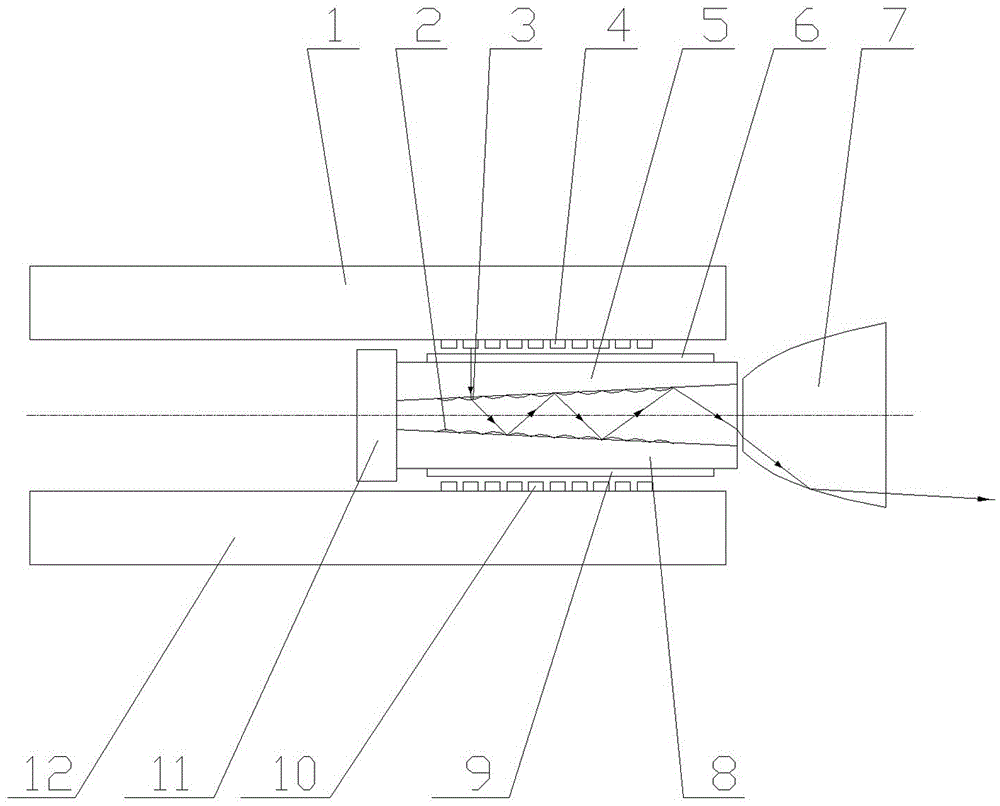
[0031] Such as figure 1 As shown, the light source assembly proposed by the present invention includes: a hollow light pipe inside and light-emitting elements arranged outside the left and right sides of the light pipe. For ease of description, the light-emitting element arranged outside the left side of the light guide is the left light-emitting element 4, the light-emitting element arranged outside the right side of the light guide is called the right light-emitting element 10, and the left light-emitting element 4 is arranged on the left circuit board 1 , the right light emitting element 10 is arranged on the right circuit board 12 .

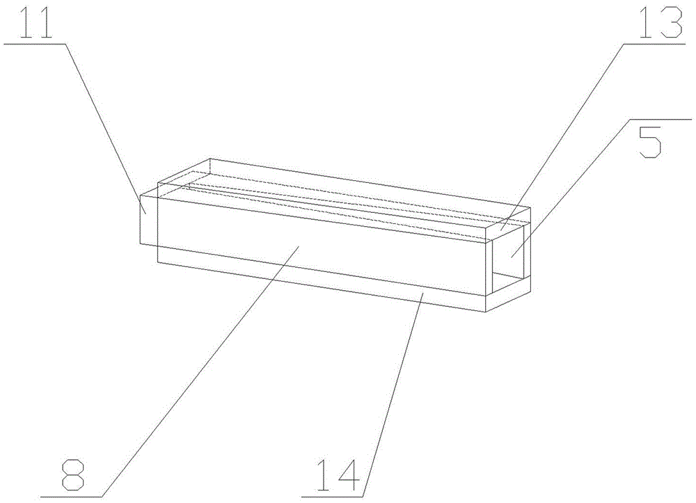
[0032] Such as figure 1 , 2 As shown, the light guide is formed by bonding the left reflector 5, the right reflector 8, the upper reflector 13, the lower reflector 14 and the rear reflector 11. The inner surfaces of all reflectors are coated with a layer of reflective film. The inner surfaces of the reflective sheet 5 and the right reflect...


PUM


Abstract

The invention discloses a light source assembly for a projection system. The light source assembly comprises the components of a light guide tube with a hollow inner part, light emitting elements which are arranged outside the left side and the right side of the light guide tube. The light guide tube is composed of a left reflector, a right reflector, an upper reflector, a lower reflector and a back reflector. The inside surfaces of the left reflector and the right reflector are oblique surfaces. The two oblique surfaces are symmetrically arranged and the distance between the two oblique surfaces gradually increase from back to front. The inner part of the light guide tube is provided with a trumpet-shaped emergent chamber with a frontward opening. The front end of the light guide tube is provided with a reflector cup. The light emitting surface of each light emitting element emits light. The light penetrates through the reflector and a phosphor powder at the light emitting surface side. After light which is excited from the phosphor powder is reflected by a reflecting film for many times in the light guide tube, the light is transmitted out of the trumpet-shaped emergent chamber. Partial light which is emergent from the trumpet-shaped emergent chamber is reflected and emitted out by the reflector cup, and the other part is directly emitted out through the reflector cup. Based on a relatively small light emitting surface, the light source assembly for the projection system has advantages of increasing power of the light source assembly and effectively improving optical efficiency of the light source assembly.

Description

technical field [0001] The invention relates to a light source assembly, in particular to a light source assembly used in a projection system. Background technique [0002] Projection systems use traditional light bulbs as light sources for a long time. Due to some inherent defects of light bulbs, projectors using light bulb systems have brought many troubles to projector consumers during use. [0003] First of all, the service life of the bulb can only be maintained for a few thousand hours, and as time goes on, the brightness of the bulb will decay. In this way, consumers need to replace the bulb when other parts of the projector except the bulb can still be used normally. , which brings additional expenses; secondly, because the bulb is a gas light source, it needs to be driven by a high-voltage driver board, and it cannot be turned on immediately, which is extremely inconvenient in practice; thirdly, the ultraviolet light and infrared light emitted by the bulb are harmfu...

Claims


Application Information

Patent Timeline
Patent Type & Authority Applications(China)
IPC IPC(8): G03B21/20
CPCG03B21/204G03B21/2066
Inventor 张建平
Owner SHENZHEN HUOLE TECH DEV CO LTD
Why Eureka
Try Eureka