Virtual-reality device with head-bio-electricity-signal-based human-computer interaction function
A bioelectrical signal, virtual reality technology, applied in the field of smart wearable devices, to achieve the effect of diversification, human-computer interaction, and increase of human-computer interaction
- Summary
- Abstract
- Description
- Claims
- Application Information
AI Technical Summary
Benefits of technology
Problems solved by technology
Method used
Image
Examples
Embodiment 1
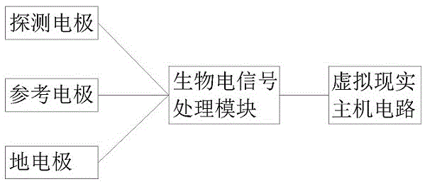
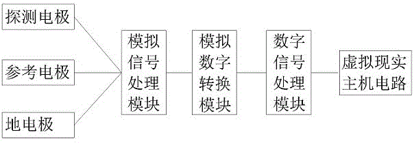
[0045] figure 2Shown is the basic structure diagram of this embodiment, as shown in the figure, the virtual reality device with human-computer interaction function based on bioelectrical signals described in this embodiment includes detection electrodes, reference electrodes, ground electrodes, analog signal A processing module, an analog-to-digital conversion module, a digital signal processing module and a virtual reality host circuit.
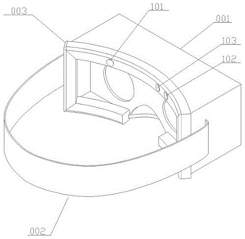
[0046] image 3 and Figure 4 Shown is a schematic diagram of the arrangement of electrodes in this embodiment, in which 001 is the main body of the virtual reality device, 002 is the headband of the virtual reality device, 003 is the sponge of the virtual reality device, 101 is the detection electrode, 102 is the reference electrode, 103 for the ground electrode.
[0047] In this embodiment, the main body 001 of the virtual reality device has a host circuit of the virtual reality device, and the detection electrode 101, the reference el...
Embodiment 2
[0056] Figure 5 Shown is the basic structure diagram of Embodiment 2. As shown in the figure, the virtual reality device with human-computer interaction function based on bioelectrical signals described in this embodiment includes detection electrodes, reference electrodes 1, reference electrodes 2, A ground electrode, an analog signal processing module, an analog-to-digital conversion module, a digital signal processing module and a virtual reality host circuit.
[0057] Figure 6 , Figure 7 and Figure 8 It is an example of electrode distribution in Embodiment 2, where 107 is reference electrode 1 and 106 is reference electrode 2 .
[0058] In this embodiment, the main body 001 of the virtual reality device has a host circuit of the virtual reality device, and the detection electrode 101 and the reference electrode 1 are connected to a differential input terminal of an amplifier circuit in the analog signal processing module through a shielded wire , the detection elec...
Embodiment 3
[0062] Figure 9 Shown is the basic structure diagram of Embodiment 3. As shown in the figure, the virtual reality device with human-computer interaction function based on bioelectric signals described in this embodiment includes detection electrode 1, detection electrode 2, and reference electrode 1. , a reference electrode 2, a ground electrode, an analog signal processing module, an analog-to-digital conversion module, a digital signal processing module and a virtual reality host circuit.
[0063] Figure 10 , Figure 11 , Figure 12 and Figure 13 It is an example of the electrode distribution scheme in the third embodiment, where 108 is the detection electrode 1 and 109 is the detection electrode 2 .
[0064] In this embodiment, the main body 001 of the virtual reality device has a host circuit of the virtual reality device, and the detection electrode 1 and the reference electrode 1 are connected to a differential input terminal of an amplifier circuit in the analog ...
PUM
 Abstract
Description
Claims
Application Information
 - R&D
- Intellectual Property
- Life Sciences
- Materials
- Tech Scout
- Unparalleled Data Quality
- Higher Quality Content
- 60% Fewer Hallucinations
Browse by: Latest US Patents, China's latest patents, Technical Efficacy Thesaurus, Application Domain, Technology Topic, Popular Technical Reports.
© 2025 PatSnap. All rights reserved.Legal|Privacy policy|Modern Slavery Act Transparency Statement|Sitemap|About US| Contact US: help@patsnap.com


