
Automatic cut-off device

A technology of automatic cutting and sliding mechanism, which is applied in the direction of sawing machine, attachment of sawing machine, metal processing equipment, etc., can solve the problem of low degree of automation, and achieve the effect of automatic cutting and preventing misoperation

Active Publication Date: 2018-11-23
安徽麦克威链传动制造有限公司 +1
View PDF5 Cites 0 Cited by
  • Summary
  • Abstract
  • Description
  • Claims
  • Application Information

AI Technical Summary

Problems solved by technology

[0003] The purpose of the present invention is to provide an automatic cutting device, which overcomes the problem of low automation of the cutting device in the prior art, and realizes the automatic cutting of the parts to be cut

Method used


Image

  • Automatic cut-off device

Examples


Embodiment Construction

[0028] Specific embodiments of the present invention will be described in detail below in conjunction with the accompanying drawings. It should be understood that the specific embodiments described here are only used to illustrate and explain the present invention, and are not intended to limit the present invention.

[0029] In the present invention, unless stated otherwise, the used orientation words such as "up, down, left, right" usually refer to figure 1 Up and down and left and right are shown. "Inner and outer" refer to the inner and outer on the specific outline. "Far and near" refer to far and near relative to a certain component.

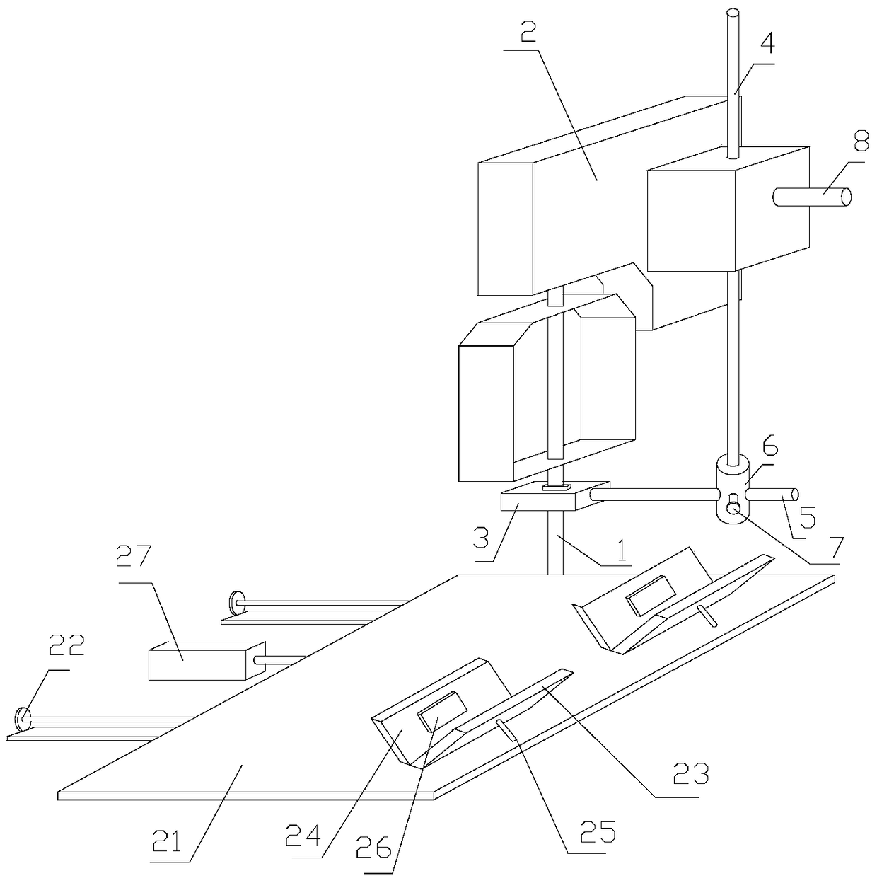
[0030] The present invention provides an automatic cutting device, which includes: a body, a base plate 21, a cylinder 27, a connecting rod, a sliding mechanism 22, a fixing mechanism, an inductor 26 and a trigger switch, and the base plate 21 is arranged on the body On one side, the fixing mechanism is arranged on the upper surface of ...


PUM


Abstract

The invention discloses an automatic cut-off device which comprises a machine body, a basal plate, an air cylinder, a connecting rod, a sliding mechanism, a fixing mechanism, an inductor and a trigger switch, wherein the basal plate is arranged at one side of the machine body; the fixing mechanism is arranged on the upper surface of the basal plate for fixing a to-be-cut part; the sliding mechanism is arranged below the basal plate; the basal plate slides along with the sliding mechanism; the air cylinder is connected to the basal plate through the connecting rod; a motion direction of the connecting rod driven by the air cylinder is the same as the direction of the sliding mechanism; the inductor is arranged on the fixing mechanism for inducting the to-be-cut part, and is electrically connected to the trigger switch for outputting a trigger signal to close the trigger switch in case of inducting the to-be-cut part; and the machine body and the air cylinder are electrically connected to the trigger switch, so that the air cylinder and the machine are electrified in case of closing the trigger switch to drive the basal plate to move to cut. The automatic cut-off device overcomes the problem that the automation degree of the cut-off device in the prior art is not high, and realizes automatic cut-off of the to-be-cut part.

Description

technical field [0001] The invention relates to the field of fixing belt cutoffs, in particular to a cutoff device. Background technique [0002] In the existing filter manufacturing field, the size of the filter shell needs to be adjusted according to the needs of the manufacturer, so a cutting machine is needed to cut off the filter shell. Since the work of the cutting machine is very dangerous, if the operation Not good, it will lead to very serious safety problems. In order to avoid potential safety hazards caused by misoperation, designing a cutting device that can automatically cut off has become a problem that needs to be solved urgently. Contents of the invention [0003] The object of the present invention is to provide an automatic cutting device, which overcomes the problem of low automation of the cutting device in the prior art, and realizes the automatic cutting of the pieces to be cut. [0004] In order to achieve the above object, the present invention pro...

Claims


Application Information

Patent Timeline
Patent Type & Authority Patents(China)
IPC IPC(8): B23D55/04B23D59/00
CPCB23D55/046B23D59/001
Inventor 胡德华
Owner 安徽麦克威链传动制造有限公司
Learn More