Anti-shock isolation control method and structure with anti-drop beam and anti-collision functions
A control method and anti-collision technology, applied in the direction of bridges, bridge parts, bridge construction, etc., can solve the problem of increased collision risk between falling beams and adjacent span main beams, large bridge structure displacement, and inability to effectively control shock-absorbing and isolating bearings, etc. problems, to achieve the effect of improving the ability to resist earthquake risks and preventing collision disasters
- Summary
- Abstract
- Description
- Claims
- Application Information
AI Technical Summary
Problems solved by technology
Method used
Image
Examples
Embodiment 1
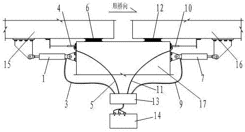
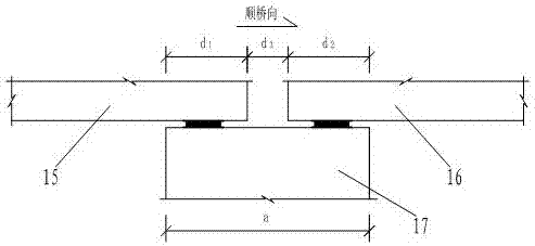
[0039] Such as figure 1 , image 3 As shown, the present invention includes a connection system I respectively located between the main girder I15 and the pier 17, a connection system II between the main girder II16 and the pier 17, a PLC intelligent control system 13 and a power supply 14, and the connection system I includes The magneto-rheological damper I1 connecting the main girder I15 and the pier 17, the displacement sensor I4 for measuring the relative displacement between the main girder I15 and the pier 17, and the support I6 between the main girder I15 and the pier 17; the connection system II includes connecting The magnetorheological damper II7 of the main girder II16 and the pier 17, the displacement sensor II10 for measuring the relative displacement of the main girder II16 and the pier 17, and the support II12 between the main girder II16 and the pier 17; the magnetorheological damper I1 The magnetorheological damper II7 is connected to the PLC intelligent con...
Embodiment 2
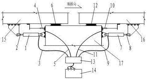
[0099] Such as figure 2 , Figure 4 As shown, the present invention includes a connection system I respectively located between the main girder I15 and the pier 17, a connection system II between the main girder II16 and the pier 17, a PLC intelligent control system 13 and a power supply 14, and the connection system I includes The magnetorheological damper I1 connecting the main girder I15 and the pier 17, the force sensor I2 located at the end of the magnetorheological damper I1, the displacement sensor I4 for measuring the relative displacement between the main girder I15 and the pier 17, and the The support I6 between 17; the connection system II includes the magnetorheological damper II7 connecting the main girder II16 and the bridge pier 17, the force sensor II8 located at the end of the magnetorheological damper II7, and measuring the main girder II16 and the bridge pier 17 The relative displacement displacement sensor II10 and the support II12 between the main girder...
PUM
 Abstract
Description
Claims
Application Information
 - R&D
- Intellectual Property
- Life Sciences
- Materials
- Tech Scout
- Unparalleled Data Quality
- Higher Quality Content
- 60% Fewer Hallucinations
Browse by: Latest US Patents, China's latest patents, Technical Efficacy Thesaurus, Application Domain, Technology Topic, Popular Technical Reports.
© 2025 PatSnap. All rights reserved.Legal|Privacy policy|Modern Slavery Act Transparency Statement|Sitemap|About US| Contact US: help@patsnap.com


