
Display panel and display device

A display panel and display area technology, applied in optics, instruments, electrical and digital data processing, etc., to achieve excellent display effects and improve the effect of man-machine communication interface

Active Publication Date: 2016-04-20
BOE TECH GRP CO LTD +1
View PDF10 Cites 8 Cited by
  • Summary
  • Abstract
  • Description
  • Claims
  • Application Information

AI Technical Summary

Problems solved by technology

However, the design of the frame structure or black ink coating constitutes a kind of border boundary to the framed image.

Method used


Image

  • Display panel and display device
  • Display panel and display device
  • Display panel and display device

Examples


Embodiment Construction

[0023] The features and principles of the present invention will be described in detail below in conjunction with the accompanying drawings, and the examples given are only used to explain the present invention, not to limit the protection scope of the present invention.

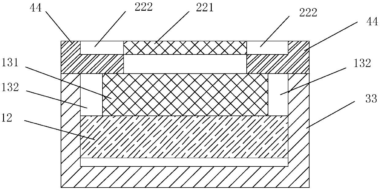
[0024] Such as figure 2 and Figure 4 As shown, the embodiment of the present invention provides a display panel, including a first substrate and a second substrate, the first substrate includes a first central display area 131 and a first edge area 132, and the second substrate includes a second central display area 131 and a first edge area 132. The display area 221, the second edge area 222,

[0025] It also includes a light guide member 44 disposed between the first substrate and the second substrate, the light guide member 44 includes a first optical component 442 partially covering above the first central display area 131, and is located on the first central display area 131. The second optical comp...


PUM


Abstract

The invention relates to a display panel. The display panel comprises a first substrate and a second substrate, wherein the first substrate comprises a first central display area and first marginal areas; the second substrate comprises a second central display area and second marginal areas. The display panel also comprises light guide components arranged between the first substrate and the second substrate, wherein the light guide components comprise first optical components and second optical components; the first optical components partially cover the top of the first central display area; the second optical components are arranged at the sides of the second marginal areas; the first optical components can enable part of light rays exiting from the first central display area to exit from the tops of the second marginal areas and enable part of light rays exiting from the first central display area to exit from the tops and sides of the second optical components. The invention also provides a display device. The display panel has the beneficial effects that images appear on the margins of the display panel by arranging the light guide components, so that the frame boundary of the display panel is weakened and a man-machine conversation interface can be greatly improved so as to provide excellent display effects.

Description

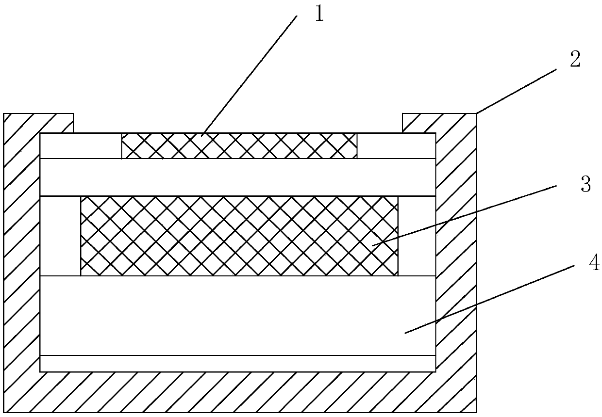
technical field [0001] The invention relates to the technical field of liquid crystal product production, in particular to a display panel and a display device. Background technique [0002] In the current field of display devices, in order to ensure effective signal transmission, we design a large number of conductive metals or other materials on the frame of the device. However, in order to avoid the visibility of the conductive lines and affect the aesthetics, the structure of the black frame is usually designed. Such as figure 1 As shown, the structure of the current display device includes a backlight 4 , a first substrate 3 , a second substrate 1 , and a frame 2 surrounding the backlight 4 and the first substrate 3 and the second substrate 1 . However, the frame structure or the black ink coating design constitutes a kind of border boundary to the framed image. Especially in today's background that people have higher and higher requirements on the quality of image di...

Claims


Application Information

Patent Timeline
IPC IPC(8): G02F1/1335
CPCG02F1/133524G06F3/041G02F1/1347G02F1/13338G02F1/133317G02F1/133308G06F3/0412
Inventor 田健胡明张贵玉
Owner BOE TECH GRP CO LTD
Learn More