Power plug

A technology of power plugs and sockets, which is applied in the direction of circuits, electrical components, coupling devices, etc., can solve problems such as sparking phenomenon, large pull-out force, force instability, etc. convenient effect

Inactive Publication Date: 2016-04-20
XIAOGAN CITY KAPULONG DAILY NECESSITIES CO LTD
View PDF7 Cites 19 Cited by
  • Summary
  • Abstract
  • Description
  • Claims
  • Application Information

AI Technical Summary

Problems solved by technology

This tends to require a high pull-out force when pulling the plug out of the socket; therefore, it makes manual removal of the plug difficult
[0003] Moreover, when pulling out manually, due to the instability of the force, it is easy to cause sparks with the electrical contacts during the process of pulling out the plug, which endangers equipment and personal safety.

Method used


Image

  • Power plug
  • Power plug

Examples


Embodiment Construction

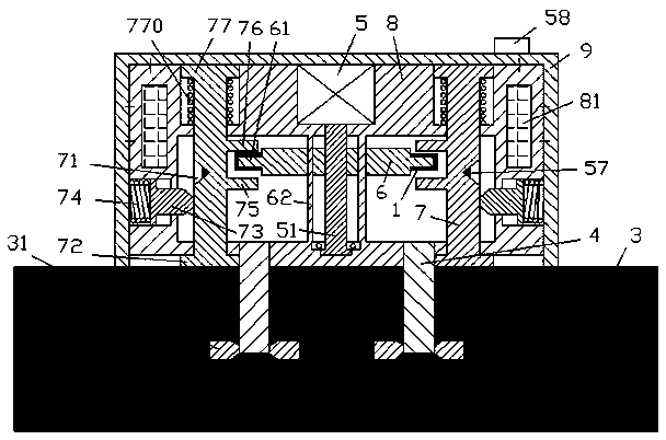
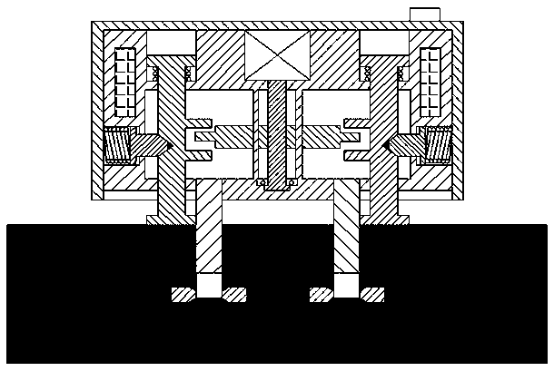
[0010] Combine below Figure 1-2 The present invention will be described in detail.

[0011] A power plug according to an embodiment includes a frame body 8 fixedly provided with an outer casing 9 and two plug pins 4 fixedly connected to the frame body 8 and symmetrically arranged left and right, and the two plug pins 4 are used to be inserted into In the hole of the socket 3 to be in electrical contact with the contacts 31 respectively, the frame body 8 can also be slidably fitted with two push-off pillars 7 arranged symmetrically on the left and right, and the structure of the two push-off pillars 7 is a mirror image Symmetrical and each of the push-off columns 7 includes a push-off column foot 72 at the lower end for engaging with the socket 3, a wedge-shaped groove on the outwardly facing side of the push-off column 7 71. The upper stressed convex plate 76 and the lower stressed convex plate 75 located on the inwardly facing side of the push-off column 7, and the limit po...


PUM


Abstract

Provided is a power plug. The power plug comprises a frame body (8) and two plug pins (4), wherein an outer shell (9) is fixed on the frame body (8), and the two plug pins are fixedly connected with the frame body and are bilaterally and symmetrically arranged. The two plug pins (4) are used for being inserted into holes of sockets (3) and are in electrical contact with contacts (31) respectively. The frame body (8) is further internally slidably matched with two symmetrically and bilaterally arranged top open post pieces (7). The structure images of the two top open post pieces (7) are symmetrical, and each top open post piece (7) comprises a top open post foot (72) arranged at the low end position of the top open post piece and used for being connected with the socket (3), a wedge-shaped groove (71) located on an outward side face of the top open post piece (7), an upper stressed convex board (76) located on an inward side face of the top open post piece (7), a lower stressed convex board (75) and a limit end portion (77) located at the upper end position and used for being connected with the outer shell (9).

Description

technical field [0001] The invention relates to the field of plugs for electrical sockets, in particular to a power plug. Background technique [0002] When the pin of the plug is in contact with the hole of the socket, in order to ensure good electrical contact and have a stable holding force, the joint between the pin and the contact usually has a strong engagement force or friction force. This tends to require a greater pull-out force when pulling the plug out of the socket; thus, it makes manual pull-out of the plug difficult. [0003] Moreover, when manually pulling out, due to the instability of the force, it is easy to cause sparks with the electrical contacts during the process of pulling out the plug, endangering equipment and personal safety. Contents of the invention [0004] The purpose of the present invention is to provide a power plug, which can overcome the defects in the prior art. [0005] An electric power plug according to the present invention includ...

Claims


Application Information

Patent Timeline
Patent Type & Authority Applications(China)
IPC IPC(8): H01R13/629H01R13/633
CPCH01R13/629H01R13/633
Inventor 周健隆
Owner XIAOGAN CITY KAPULONG DAILY NECESSITIES CO LTD
Why Eureka
Try Eureka