Supercharge Your Innovation With Domain-Expert AI Agents!

A Speed ​​Tracking System of Rotating Mechanism

A technology of rotating mechanism and tracking system, applied in the direction of control system, vector control system, electromechanical device, etc., can solve the problems affecting the work efficiency and achieve the effect of smooth switching

Active Publication Date: 2018-02-23
江苏众建达丰机械工程有限公司
View PDF10 Cites 0 Cited by
  • Summary
  • Abstract
  • Description
  • Claims
  • Application Information

AI Technical Summary

Problems solved by technology

[0003] There are two types of speed identification methods for speed tracking function: hardware identification method and software identification method. These methods need 2 to 3 seconds from the start of the frequency converter to the successful identification. If the operator of the portal crane is in place at a low speed If the mechanical brake and frequency converter are switched frequently, the time required for speed identification will greatly affect the work efficiency

Method used


Image

  • A Speed ​​Tracking System of Rotating Mechanism
  • A Speed ​​Tracking System of Rotating Mechanism

Examples


Embodiment Construction

[0018] The present invention will be further described below in conjunction with the accompanying drawings and embodiments.

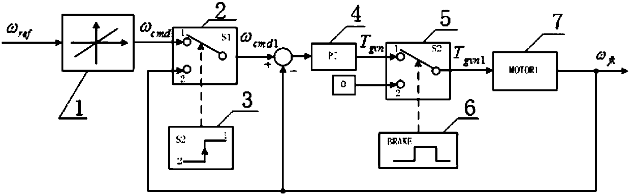
[0019] A speed tracking system for a rotating mechanism ( figure 1 ), including a slope conversion unit 1, a first switch 2, a PI regulator 4, a second switch 5 and a motor 7;

[0020] Speed ​​command reference value ω ref The slope conversion unit 1 generates the first rotation speed command value ω whose rate of change can be set cmd ;

[0021] The first changeover switch 2 receives the first rotational speed command value ω cmd and motor 7 speed feedback value ω fk , output the second rotational speed command value ω cmd1 , the second speed command value ω is controlled by the second switch state 3 signal cmd1 Equal to the first rotational speed command value ω cmd Or motor 7 speed feedback value ω fk ; When the second switch 5 is in the control state of the frequency converter, the second switch 5 feedbacks the value ω from the speed of the ...


PUM


Abstract

The invention discloses a rotating speed tracking system of a rotary mechanism. The rotating speed tracking system comprises a motor, a frequency converter, and a braking system. The motor is controlled by the frequency converter and the braking system. The frequency converter is provided with a slope conversion unit, a first change-over switch, a PI regulator, and a second change-over switch. When the system switches to mechanical braking, the frequency converter does not influence a mechanical braking effect or report faults. When the system switches to the frequency converter, almost no rotating speed identification time is required.

Description

technical field [0001] The invention relates to a rotation speed tracking system, in particular to a rotation speed tracking control system of a rotation mechanism when the mechanical brake of a rotation mechanism with large inertia is switched and controlled by a frequency converter. Background technique [0002] At present, on the rotating mechanism of the large inertia load type, such as the rotating mechanism of the gantry crane, the frequency converter is generally used to drive the motor to drive the rotating mechanism, and it is also equipped with a mechanical brake, which is adjusted by hydraulic control. strength. Since the frequency converter generally adopts speed control, it is impossible to achieve precise position control. Usually, when the rotating mechanism stops and needs to be positioned, the operator of the portal crane often uses the frequency converter and the mechanical brake to switch control to achieve the purpose of accurate positioning. In order to...

Claims


Application Information

Patent Timeline
Patent Type & Authority Patents(China)
IPC IPC(8): H02P21/18H02P21/20H02K7/10
CPCH02K7/1008
Inventor 谢鸣李小松曾国庆毛荣芳
Owner 江苏众建达丰机械工程有限公司
Features
  • R&D
  • Intellectual Property
  • Life Sciences
  • Materials
  • Tech Scout
  • Unparalleled Data Quality
  • Higher Quality Content
  • 60% Fewer Hallucinations
Learn More