
Cleaning device of automatic cleaning machinery

A cleaning device and automatic cleaning technology, applied in cleaning machinery, manual sweeping machinery, cleaning equipment, etc., can solve problems such as inability to effectively spray the surface to be cleaned, leaving water stains on the surface to be cleaned, and prone to splashing.

Inactive Publication Date: 2016-04-27
郑子繁
View PDF7 Cites 2 Cited by
  • Summary
  • Abstract
  • Description
  • Claims
  • Application Information

AI Technical Summary

Problems solved by technology

[0002] The current cleaning devices of sweeping machines, floor washing machines, window cleaning machines and curtain wall cleaning machines use brush rollers to rub the surface to be cleaned. Since there is no water or detergent (hereinafter collectively referred to as cleaning liquid) to participate, stains cannot be effectively removed
[0003] Or add a rag to the machine and drag it on the surface to be cleaned. The rag is connected to the container containing the cleaning liquid through a capillary tube. Using the capillary phenomenon of the rag, the cleaning liquid is immersed in the rag. The cleaning liquid flows to the surface to be cleaned, because the liquid on the rag cannot be controlled, it is easy to leave water stains of different sizes on the surface to be cleaned, the rag drags, and the contact time with the surface to be cleaned is short, and the dirt can only Partially sticks to the rag, less effective on dirty cleaning
[0004] Or the brush roller and the nozzle cooperate to clean the object to be cleaned. There is a hole on the nozzle pipe, and the cleaning liquid is sprayed from the hole to the brush roller or the surface to be cleaned through the pressure. When the pressure is small, the range of the sprayed liquid becomes smaller, and finally flows on the surface of the nozzle, which cannot be effectively sprayed to the surface to be cleaned, and is easy to leave water stains on the surface to be cleaned. When the pressure increases, the sprayed liquid flows on the surface to be cleaned It is easy to splash, and the above phenomenon will occur when the nozzle starts and stops, which will affect the cleaning effect

Method used


Image

  • Cleaning device of automatic cleaning machinery
  • Cleaning device of automatic cleaning machinery
  • Cleaning device of automatic cleaning machinery

Examples


Embodiment Construction

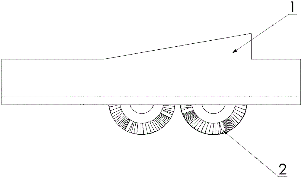
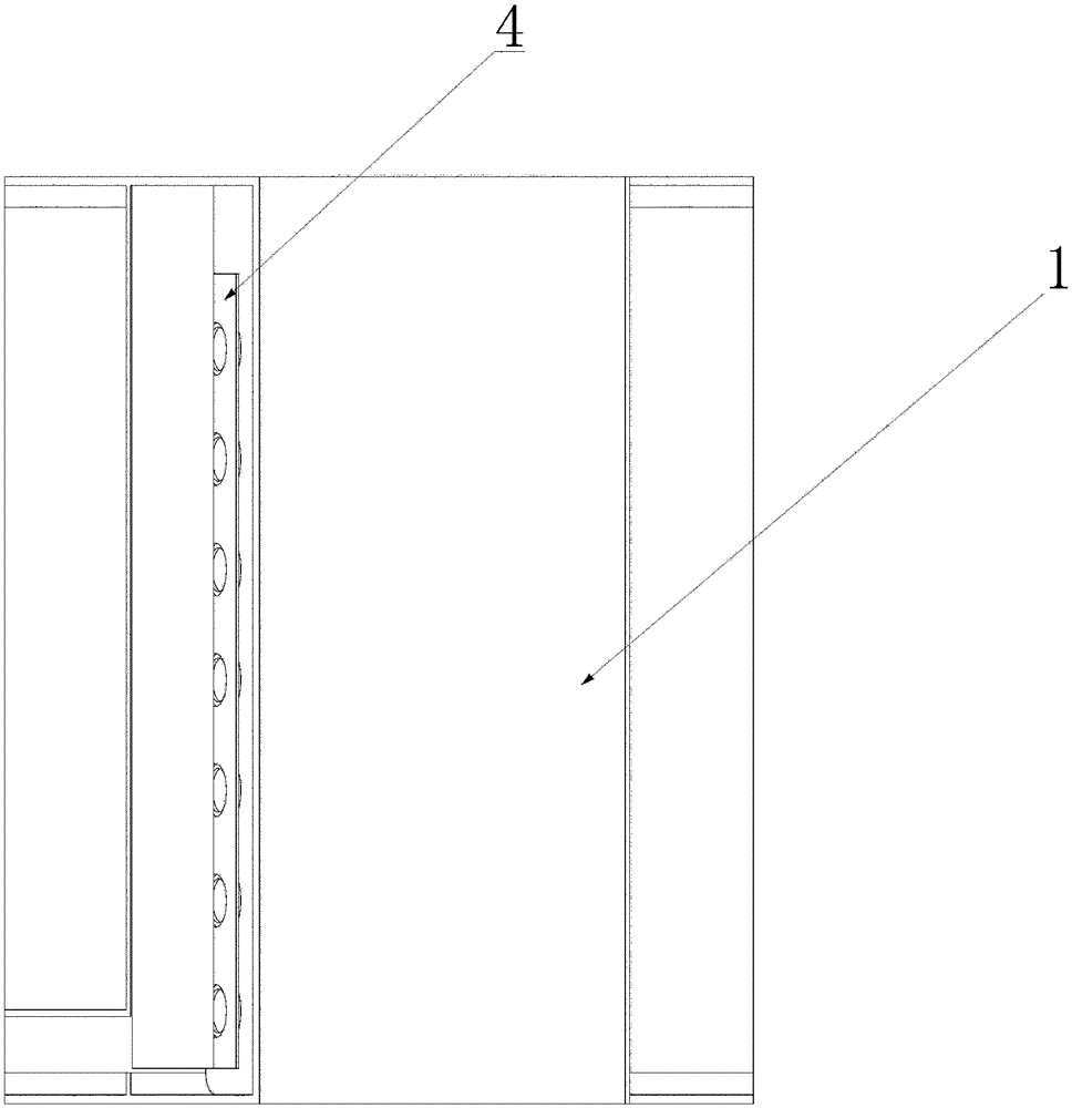
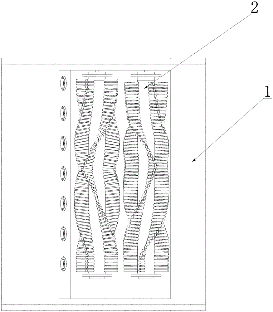
[0022] The cleaning device in this embodiment is mainly composed of a brush roller 2, a microporous atomizing sheet 3, and a housing 1;

[0023] like Figure 10 As shown, when the device mainly moves horizontally (such as a mopping machine), the cleaning liquid flows through the groove where the capillary liquid guide strip 5 is located and fills it to a suitable height, and the capillary liquid guide strip 5 acts as a liquid guide in the device , also play a role in preventing excessive cleaning liquid from overflowing the device in a flowing state, or use the capillary liquid guide strip 5 to contact the microporous atomizing sheet 3 to transfer the cleaning liquid; when the device is not mainly based on horizontal movement (such as wiping Glass robot, curtain wall cleaning), the cleaning liquid is mainly transferred to the microporous atomizing sheet 3 through the contact of the capillary liquid guide strip 5 and the microporous atomizing sheet 3; Figure 10 The middle arr...


PUM


Abstract

The invention relates to a cleaning device of automatic cleaning machinery. The cleaning device is mainly composed of porous atomizing sheets, brushing rollers and a housing, wherein the porous atomizing sheets are located on the brushing roller sides of contact surfaces constituted by the brushing rollers and a to-be-cleaned plane, and the brushing rollers are located between the housing and the to-be-cleaned plane; and the housing comprises a cleaning machine, a device shell and a surface which is connected to and fixed to the brushing rollers. The cleaning device is applicable to domestic washing or sweeping machinery, in particular to flexible floor washing machinery (a sweeper) as well as machinery for window cleaning (a window cleaning robot), wall (curtain wall) cleaning and the like, and is applicable to machinery for floor cleaning (a floor scrubber) such as street cleaning, rail cleaning and the like in such public facilities as markets and airports as well as other cleaning; and the cleaning device has the characteristics of being adjustable in cleaning degree and free from water spots on the to-be-cleaned plane after cleaning.

Description

technical field [0001] The invention relates to a cleaning device for an automatic cleaning machine, which is applied to household washing or cleaning machines, especially motorized floor washing machines (sweeping machines, mopping machines), window cleaning (glass-cleaning robots), Cleaning device for cleaning machines such as walls (curtain walls). Background technique [0002] The current cleaning devices of sweeping machines, floor washing machines, window cleaning machines and curtain wall cleaning machines use brush rollers to rub the surface to be cleaned. Since there is no water or detergent (hereinafter collectively referred to as cleaning liquid) to participate, stains cannot be effectively removed. [0003] Or add a rag to the machine and drag it on the surface to be cleaned. The rag is connected to the container containing the cleaning liquid through a capillary tube. Using the capillary phenomenon of the rag, the cleaning liquid is immersed in the rag. The cle...

Claims


Application Information

Patent Timeline
IPC IPC(8): A47L1/02A47L11/03A47L11/10A47L11/24A47L11/38
CPCA47L1/02A47L11/03A47L11/10A47L11/24A47L11/38
Inventor 郑子繁
Owner 郑子繁
Learn More