Nail pulling device

A nail puller and chute technology, applied in the field of medical devices, can solve the problems of inability to hold the nails independently, the nail puller is attached to other objects, etc., and achieve the effect of not easily removing the nail, continuous nail pulling process, and firm nail holding.

Active Publication Date: 2016-04-27
BEIJING NATON TECH GRP CO LTD
View PDF5 Cites 5 Cited by
  • Summary
  • Abstract
  • Description
  • Claims
  • Application Information

AI Technical Summary

Problems solved by technology

[0004] The invention mainly solves the technical problem that the nail puller in the prior art needs

Method used


Image

  • Nail pulling device
  • Nail pulling device
  • Nail pulling device

Examples


Embodiment approach 1

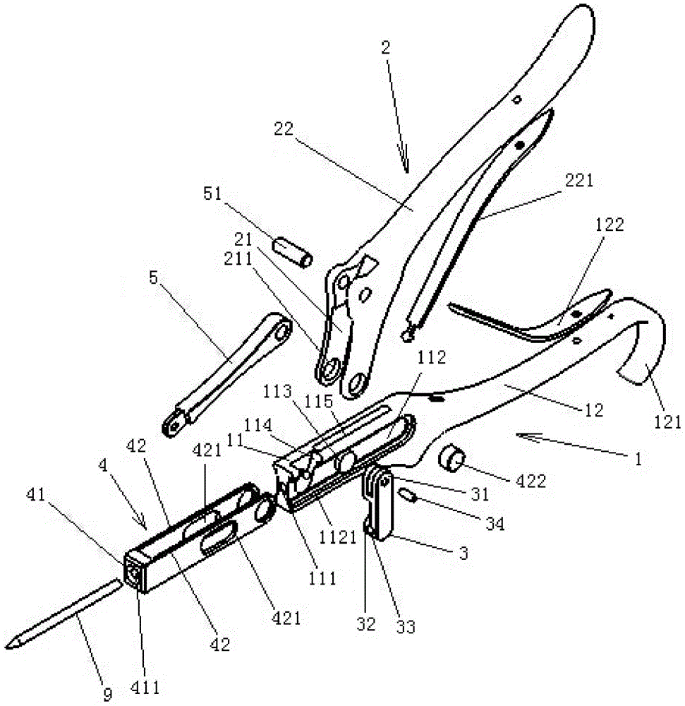
[0034] like figure 1 Shown is an embodiment of the nail puller proposed by the present invention. In Embodiment 1, the nail puller mainly includes: a first pliers body 1 , a locking block 3 , a sliding part 4 , a second pliers body 2 and a connecting rod 5 .

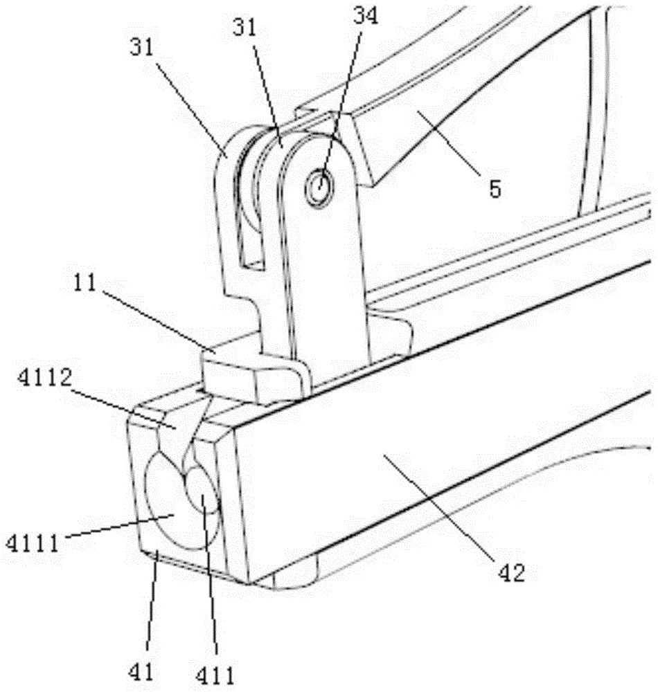
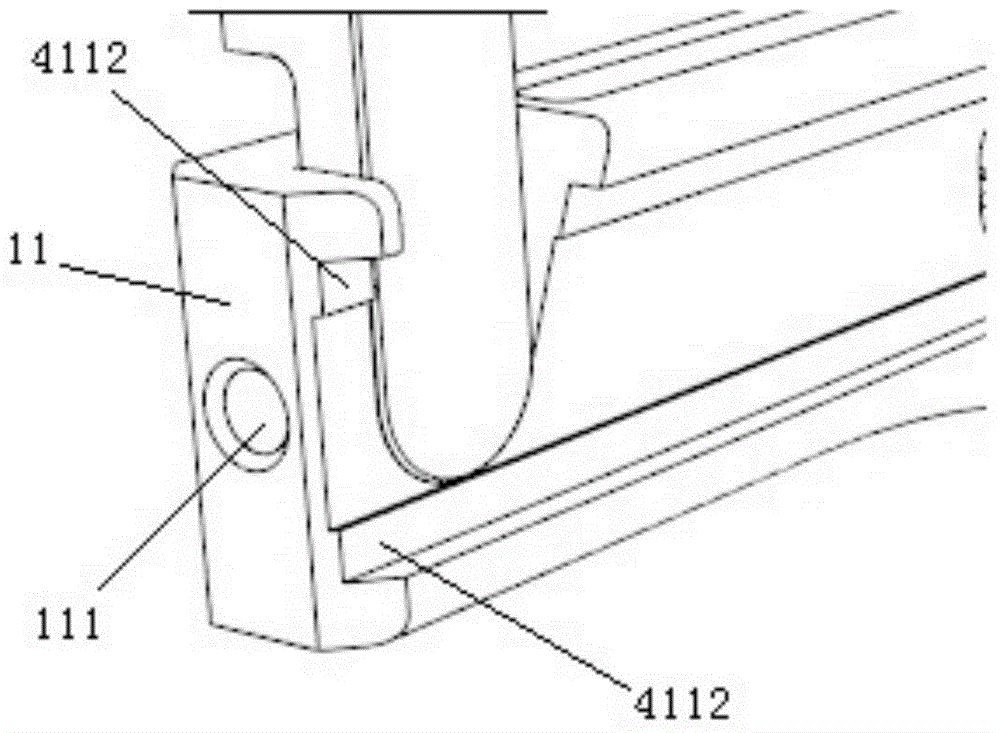
[0035] like figure 1 As shown, in the first embodiment, the first pliers body 1 has a chute portion 11 and a first pliers handle 12 formed at the rear end thereof, and the middle portion of the chute portion 11 is provided with a passage along the longitudinal direction for accommodating the fixing nail. The hole 111 and the two sides of the chute part 11 are provided with opposite chute 112, and the chute 112 is provided with two limiting protrusions 113, which are respectively arranged on the opposite surface of the chute 112, and there is a certain distance between the two limiting protrusions 113 , so that the nail can pass through it. Of course, only setting the limiting protrusion 113 on one side of the chute ca...

Embodiment approach 2

[0045] like Image 6 Shown, another embodiment of the nail puller of the present invention. In Embodiment 2, the nail puller mainly includes: a first pliers body 6 , a locking block, a sliding part 8 , a pin shaft 7 , a second pliers body and a connecting rod.

[0046] like Image 6 As shown, in Embodiment 2, the first pliers body 6 has a chute portion and a first pliers handle formed at its rear end, the middle part of the chute portion is provided with a longitudinal via hole, and the two sides of the chute portion are provided with There are opposite sliding grooves, the rear end of the sliding groove part is provided with a long hole 611 passing through transversely, and the front part of the sliding groove part is provided with a locking groove. like Figure 8 As shown, in the second embodiment, a through groove 612 is vertically opened in the middle of the chute portion, and the rear end of the through groove 612 opens at the rear end of the chute portion. The struct...


PUM


Abstract

The invention provides a nail pulling device. The nail pulling device is characterized in that a first pliers body is provided with a slide groove part and a first pliers handle formed at the rear end of the first pliers body, a longitudinal via hole is formed in the middle of the slide groove part, opposite slide grooves are formed in two sides of the slide groove part, each slide groove is provided with a limit protruding block, and a locking groove is formed in the front portion of the slide groove part; a locking block is rotatably arranged in the locking groove, the lower end of the locking block is accommodated in the locking groove and provided with a locking hole corresponding to the via hole, and the upper end of the locking block is exposed out of the locking groove; a slide part is provided with an end plate and two slide plates, the end plate is provided with an end hole corresponding to the via hole, the two slide plates are respectively slidably clamped with the two slide grooves and respectively provided with long holes corresponding to the two limit protruding blocks; a second pliers body is provided with two connecting plates, the rear ends of the connecting plates are connected and extend in a backward bending manner to form a second pliers handle, and the front ends of the two connecting plates are rotatably connected to the rear ends of the two slide plates; two ends of a connecting rod are respectively rotatably connected to the middles of the two connecting plates and the upper end of the locking block. The nail pulling device is labor saving in nail pulling and firm in nail clamping.

Description

technical field [0001] The invention relates to the technical field of medical instruments, in particular to a nail puller used for extracting or clamping fixation nails in joint or trauma surgery. Background technique [0002] The existing clamping nail puller adopts the clamping structure principle, and needs to use the hand to directly pull out the fixing nail. This kind of nail pulling device is relatively laborious in the process of pulling the nail and the user needs to rotate the fixing nail to make it withdraw. It will cause damage to the drill hole on the bone, and the fixation nail is prone to loosening during the extraction process. [0003] In order to reduce the complexity of the surgical operation and facilitate the user to quickly and labor-savingly pull out the nails during the operation, a nail puller is needed, which can help the user significantly solve the problem of laborious rotation of the entire arm when using a traditional nail puller , It can also ...

Claims


Application Information

Patent Timeline
IPC IPC(8): A61B17/92
Inventor 李文钊付明俊
Owner BEIJING NATON TECH GRP CO LTD
Why Eureka
Try Eureka