Termite automatic detection and inducing tube

A technology for automatic detection and termites, which is applied to devices for catching or killing insects, applications, animal husbandry, etc. It can solve problems such as cumbersome operations, complex structures, and missed control periods, so as to reduce use costs, enhance lure effects, and improve Ornamental effect

Inactive Publication Date: 2016-05-04
安徽康宇生物科技工程有限公司
View PDF4 Cites 5 Cited by
  • Summary
  • Abstract
  • Description
  • Claims
  • Application Information

AI Technical Summary

Problems solved by technology

Although this utility model has less pollution, longer service life and can be reused many times, it also has the following disadvantages: the device only has bait on the bait rack, and the lure effect on termites is not strong; the top cover needs to be unscrewed during detection, The operation is cumbersome, and the activity of termites cannot be known anytim

Method used


Image

  • Termite automatic detection and inducing tube
  • Termite automatic detection and inducing tube

Examples


Embodiment Construction

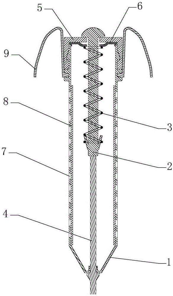
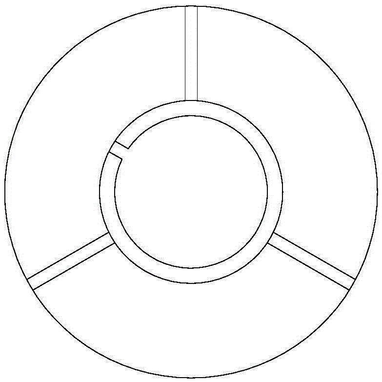
[0025] Such as figure 1 and figure 2 as shown, figure 1 It is a sectional view of the termite automatic detection lure tube proposed by the present invention, figure 2 for figure 1 Schematic diagram of the waterproof cover in .

[0026] refer to figure 1 and figure 2 , the termite automatic detection lure tube that the present invention proposes, comprises: shell 1, spring fixing pin 2, spring 3, papery bar 4 and top cover 5, wherein:

[0027] The inside of the housing 1 is provided with a cavity, one end of the housing 1 is provided with an opening communicating with the cavity, the end of the housing 1 away from the opening is provided with a first through hole communicating with the cavity, and the housing 1 is provided with a plurality of fourth through holes. Hole rows 7, each fourth through hole row 7 is arranged at intervals around the cavity of the housing 1, and in each fourth through hole row 7, any row of the fourth through hole row 7 has a plurality of ope...


PUM


Abstract

The invention discloses a termite automatic detection and inducing tube which comprises a shell, a spring fixing pin, a spring and a connecting piece. One end of the shell is open, the other end of the shell is provided with a first through hole, the interior of the shell is a cavity, and a top cover is installed at the open end of the shell. A spring ejection plate is assembled between the open end and the top cover, a stop block is arranged at one end of the spring fixing pin, an elastic buckle is arranged at the other end of the spring fixing pin, the spring fixing pin penetrates through the top cover and the spring ejection plate, the stop block is located on the side, far away from the cavity, of the top cover, and the elastic buckle extends into the cavity. The spring fixing pin is sleeved with the spring, one end of the spring is connected with the spring ejection plate, and the other end of the spring is connected with the elastic buckle. One end of the connecting piece penetrates through the first through hole and is connected with the spring fixing pin, and the other end of the connecting piece is fixed to the outer side of the shell. When the connecting piece is bitten by termites to a certain degree, the spring pulls the connecting piece broken, the stop block is separated from the upper end face of the top cover, workers can judge that the termites move in the area after seeing the condition, and accordingly the aim of automatic detection is achieved.

Description

technical field [0001] The invention relates to the technical field of termite automatic detection, in particular to a termite automatic detection lure tube. Background technique [0002] The harm of termites is extensive and serious. The objects they harm are hidden and difficult to be found. The surface of the harmed objects looks intact, but in fact they are riddled with holes. Once they are found, they have already caused losses, and their food is very wide. Cellulose-containing substances are the food of termites, so people's clothing, food, housing, transportation and use all suffer from it. Termites harm houses and buildings, decorations, storage materials, cotton and linen products, books, railway sleepers, etc., and even harm river embankments and reservoir earth dams, causing serious damage to breaking dikes and crossing dams. [0003] For a long time, the method of controlling termites is to use chemical control, such as applying insecticide liquid to the soil. T...

Claims


Application Information

Patent Timeline
IPC IPC(8): A01M1/02A01M1/20
CPCA01M1/02A01M1/20
Inventor 芮有春
Owner 安徽康宇生物科技工程有限公司
Why Eureka
Try Eureka