Multi-angle continuous THz wave illumination digital holographic imaging method

A technology of digital holography and digital hologram, applied in the direction of instruments, etc., can solve the problem of losing sample information

Active Publication Date: 2016-05-04
BEIJING UNIV OF TECH
View PDF6 Cites 16 Cited by
  • Summary
  • Abstract
  • Description
  • Claims
  • Application Information

AI Technical Summary

Problems solved by technology

However, during the experiment, affected by the size of the pyroelectric detector, only the frequency information of some samples was recorded, and a lot of important sample information was lost.

Method used


Image

  • Multi-angle continuous THz wave illumination digital holographic imaging method
  • Multi-angle continuous THz wave illumination digital holographic imaging method
  • Multi-angle continuous THz wave illumination digital holographic imaging method

Examples


Embodiment Construction

[0014] Exemplary embodiments and features of the present invention will be described in detail below with reference to the accompanying drawings.

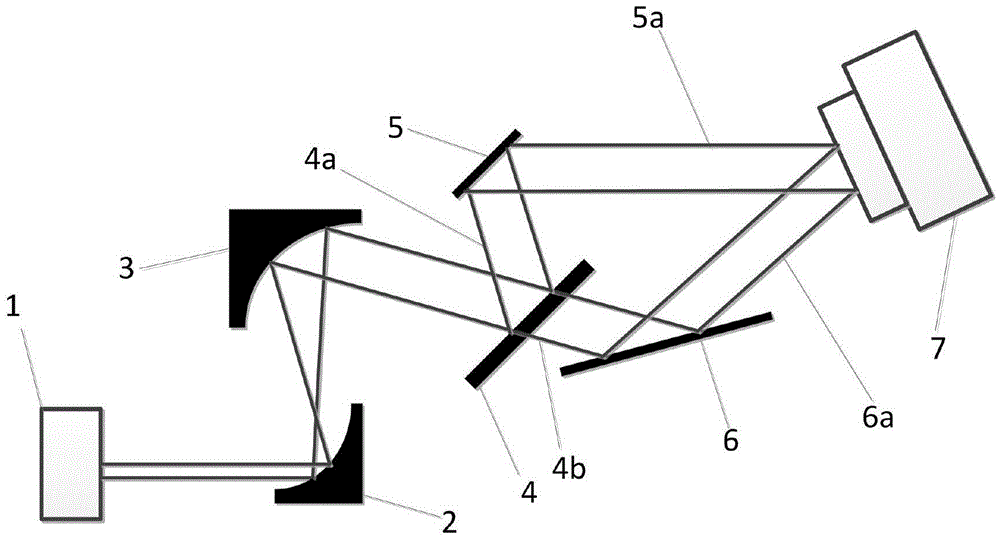
[0015] A multi-angle continuous terahertz wave illumination digital holographic imaging system, the optical path of which includes CO 2 Pump terahertz laser 1, first gold-coated off-axis mirror 2 (focal length 25.4mm), second gold-coated off-axis mirror 3 (focal length 76.2mm), silicon wafer 4, test sample 5, gold-coated reflector mirror 6, pyroelectric detector 7, as figure 1 shown. Experimental terahertz laser CO 2 The pumping terahertz laser 1 has a frequency of 2.52THz (corresponding to a central wavelength of 118.83μm), which can generate continuous terahertz waves with an average power of 150mW. The number of pixels of the pyroelectric detector 7 is 320×320 pixels. The size is 80 μm × 80 μm, and the sampling frequency is 48 Hz.

[0016] The measured sample 5 of the imaging test is a coin, and the size of the hologram dete...


PUM


Abstract

The invention provides a multi-angle continuous THz wave illumination digital holographic imaging method. The method comprises the following steps: obtaining the frequency spectrum of a hologram through Fourier transform; taking multiple holograms while changing the illumination light of a sample so as to obtain the frequency spectra of the multiple holograms; overlapping the obtained frequency spectra of the multiple holograms and carrying out inverse Fourier transform to obtain a combined hologram; and carrying out object light filed reconstruction using an angular spectrum reconstruction method to finally obtain a combined digital holographic reconstructed image. With adoption of the method, a THz digital holographic imaging system can obtain more object light frequency information, resulting in the improvement of the imaging resolution of the device; a combined spectrogram is subjected to inverse Fourier transform to obtain the combined hologram and therefore obtain the reconstructed image containing more sample frequency spectrum information.

Description

technical field [0001] The invention relates to a method for improving the resolution of digital holography, in particular to a method for multi-angle continuous terahertz wave illumination digital holographic imaging. Background technique [0002] Continuous terahertz wave digital holography is the product of the combination of traditional optical holography, computer technology and pyroelectric detection technology. The numerical reproduction of the recorded object is realized by computer simulation of the optical diffraction process. However, during the experiment, due to the influence of the size of the pyroelectric detector, only the frequency information of some samples was recorded, and a lot of important sample information was lost. The method of improving imaging resolution by multi-angle illumination is carried out without changing the parameters of system components such as detector size and number of pixels. By changing the incident angle of the terahertz wave ...

Claims


Application Information

Patent Timeline
Patent Type & Authority Applications(China)
IPC IPC(8): G03H1/08G03H1/22
CPCG03H1/0866G03H1/2286
Inventor 戎路王红红王大勇王云新
Owner BEIJING UNIV OF TECH
Why Eureka
Try Eureka